Electrical characteristics (continued) – Rainbow Electronics MAX1421 User Manual
Page 3
MAX1421
12-Bit, 40Msps, +3.3V, Low-Power ADC
with Internal Reference
_______________________________________________________________________________________
3
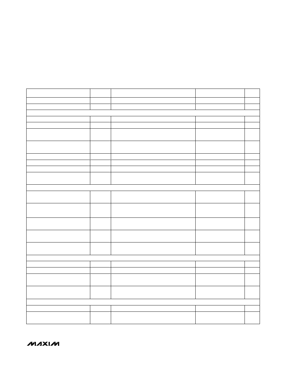
ELECTRICAL CHARACTERISTICS (continued)
(V
AVDD
= V
DVDD
= +3.3V, AGND = DGND = 0, V
IN
= ±1.024V, differential input voltage at -0.5dB FS, internal reference,
f
CLK
= 40MHz (50% duty cycle), digital output load C
L
≈ 10pF, T
A
= T
MIN
to T
MAX
, unless otherwise noted. Typical values are at
T
A
= +25°C.)
PARAMETER
SYMBOL
CONDITIONS
MIN
TYP
MAX
UNITS
Differential Gain
DG
±1
%
Differential Phase
DP
±0.25
degrees
ANALOG INPUTS (INP, INN, CML)
Input Resistance
R
IN
Either input to ground
32.5
k
Ω
Input Capacitance
C
IN
Either input to ground
4
pF
Common-Mode Input Level,
(Note 5)
V
CML
V
AVDD
× 0.5
V
Common-Mode Input Voltage
Range, (Note 5)
V
CMVR
V
CML
±5%
V
Differential Input Range
V
IN
V
INP
- V
INN
(Note 6)
±V
DIFF
V
Small-Signal Bandwidth
BW
-3dB
(Note 7)
400
MHz
Large-Signal Bandwidth
FPBW
-3dB
(Note 7)
150
MHz
Over-Voltage Recovery
OVR
1.5
✕
FS input
1
Clock
Cycle
INTERNAL REFERENCE (REFIN bypassed with 0.22µF in parallel with 1nF)
Common-Mode Reference Input
Voltage
V
CML
At CML
V
AVDD
✕
0.5
V
Positive Reference Voltage
Range
V
REFP
At REFP
V
CML
+ 0.512
V
Negative Reference Voltage
Range
V
REFN
At REFN
V
CML
- 0.512
V
Differential Reference Voltage
Range
V
DIFF
V
DIFF
= V
REFP
- V
REFN
1.024
±5%
V
Differential Reference
Temperature Coefficient
REFTC
±100
ppm/
°C
EXTER N AL R EF ER EN C E
REFIN Input Resistance
R
IN
(Note 8)
5
k
Ω
REFIN Input Capacitance
C
IN
10
pF
REFIN Reference Input Voltage
V
REFIN
2.048
±10%
V
Differential Reference Voltage
V
DIFF
V
DIFF
= (V
REFP
- V
REFN
)
0.95
✕
V
REFIN
/2
V
REFIN
/2
1.05
✕
V
REFIN
/2
V
EXTERNAL REFERENCE (V
REFIN
= AGND, reference voltage applied to REFP, REFN and CML)
REFP, REFN, CML Input Current
I
IN
-200
200
µA
REFP, REFN, CML Input
Capacitance
C
IN
15
pF