Pmics with dynamic core for pdas and smart phones, Electrical characteristics (continued) – Rainbow Electronics MAX1587A User Manual
Page 5
MAX1586A/MAX1586B/MAX1587A
High-Efficiency, Low-I
Q
PMICs with
Dynamic Core for PDAs and Smart Phones
_______________________________________________________________________________________
5
PARAMETER
CONDITIONS
MIN
TYP
MAX
UNITS
LBI = IN (for preset)
3.51
3.6
3.69
LBI Threshold (Falling)
MAX1586 hysteresis is
5% (typ)
With resistors at LBI
0.98
1.00
1.02
V
DBI = IN (for preset)
3.024
3.15
3.276
DBI Threshold (Falling)
MAX1586 hysteresis is
5% (typ)
With resistors at LBI
1.208
1.232
1.256
V
RSO Threshold (Falling)
Voltage on REG7, hysteresis is 5% (typ)
2.25
2.41
2.56
V
RSO Deassert Delay
61
65.5
70
ms
LBI Input Bias Current
MAX1586
-50
-5
nA
DBI Input Bias Current
MAX1586
15
50
nA
Thermal-Shutdown Temperature
T
J
rising
+160
°C
Thermal-Shutdown Hysteresis
15
°C
LOGIC INPUTS AND OUTPUTS
LBO, DBO, POK, RSO, SDA Output
Low Level
2.6V
≤
V7
≤
5.5V, sinking 1mA
0.4
V
LBO, DBO, POK, RSO Output Low
Level
V7
= 1V, sinking 100µA
0.4
V
LBO, DBO, POK, RSO Output-High
Leakage Current
Pin
= 5.5V
0.2
µA
ON_, SCL, SDA, SLP, PWM3, MR,
SRAD Input High Level
2.6V
≤
V
IN
≤
5.5V
1.6
V
ON_, SCL, SDA, SLP, PWM3, MR,
SRAD Input Low Level
2.6V
≤
V
IN
≤
5.5V
0.4
V
ON_, SCL, SDA, SLP, PWM3, MR,
SRAD Input Leakage Current
Pin = GND, 5.5V
1
1
µA
SERIAL INTERFACE
Clock Frequency
400
kHz
Bus-Free Time Between START and
STOP
1.3
µs
H ol d Ti m e Rep eated S TART C ond i ti on
0.6
µs
CLK Low Period
1.3
µs
CLK High Period
0.6
µs
S etup Ti m e Rep eated S TART C ond i ti on
0.6
µs
DATA Hold Time
0
µs
DATA Setup Time
100
ns
Maximum Pulse Width of Spikes that
Must be Suppressed by the Input
Filter of Both DATA and CLK Signals
50
ns
Setup Time for STOP Condition
0.6
µs
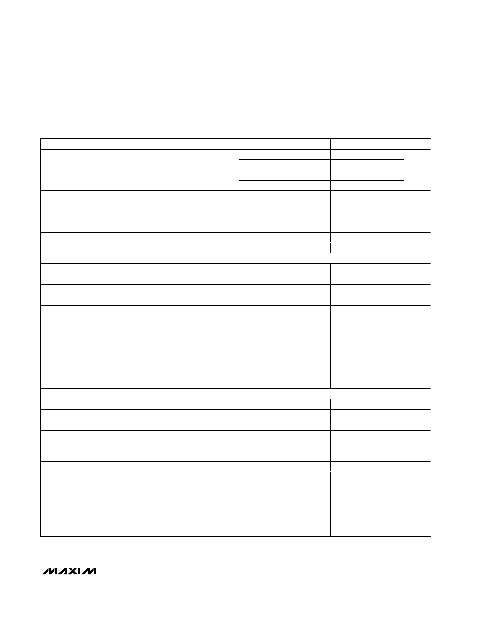
ELECTRICAL CHARACTERISTICS (continued)
(V
IN
= 3.6V, V
BKBT
= 3.0V, V
LBI
= 1.1V, V
DBI
= 1.35V, circuit of Figure 5,
T
A
= 0°C to +85°C, unless otherwise noted. Typical values
are at T
A
= +25
°C.)