Pmics with dynamic core for pdas and smart phones, Applications information – Rainbow Electronics MAX1587A User Manual
Page 27
MAX1586A/MAX1586B/MAX1587A
High-Efficiency, Low-I
Q
PMICs with
Dynamic Core for PDAs and Smart Phones
______________________________________________________________________________________
27
Note that the pole cancellation does not have to be
exact. R
C
x C
C
need only be within 0.75 to 1.25 times
R
LOAD
x C
OUT
. This provides flexibility in component
selection.
If the output filter capacitor has significant ESR, a zero
occurs at:
Z
ESR
= 1 / (2π x C
OUT
x R
ESR
)
If Z
ESR
> f
C
, it can be ignored, as is typically the case
with ceramic or polymer output capacitors. If Z
ESR
is
less than f
C
, it should be cancelled with a pole set by
capacitor C
P
connected from CC_ to GND:
C
P
= C
OUT
R
ESR
/ R
C
If C
P
is calculated to be < 10pF, it can be omitted.
Optimizing Transient Response
In applications that require load-transient response to
be optimized in favor of minimum component values,
increase the output filter capacitor to increase the R in
the compensation RC. From the equations in the previ-
ous section, doubling the output cap allows a doubling
of the compensation R, which then doubles the tran-
sient gain.
Applications Information
Backup-Battery and V7 Configurations
The MAX1586/MAX1587 include a backup-battery con-
nection, BKBT, and an output, V7. These can be utilized
in different ways for various system configurations.
Primary Backup Battery
A connection with a primary (nonrechargeable) lithium
coin cell is shown in Figure 5. The lithium cell connects to
BKBT directly. V7 powers the CPU VCC_BATT from either
V1 (if enabled) or the backup battery. It is assumed
whenever the main battery is good, V1 is on (either with
its DC-DC converter or sleep LDO) to supply V7.
No Backup Battery (or Alternate Backup)
If no backup battery is used, or if an alternate backup
and VCC_BATT scheme is used that does not use the
MAX1586/MAX1587, then BKBT should be biased from
IN with a small silicon diode (1N4148 or similar, as in
Figure 6). BKBT must still be powered when no backup
battery is used because DBO, RSO, and POK require
this supply to function. If BKBT is not powered, these
outputs do not function and are high impedance.
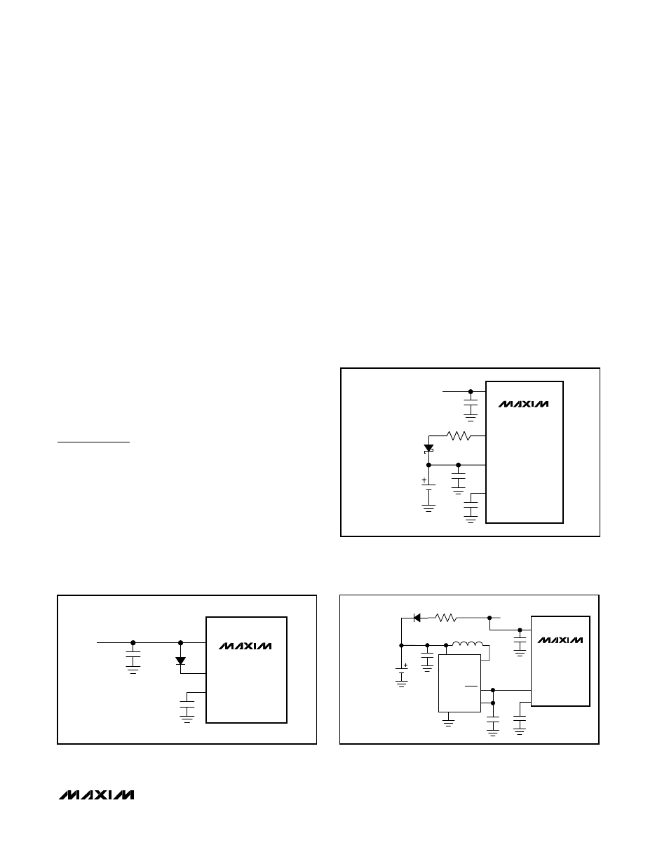
Rechargeable Li+ Backup Battery
If more backup power is needed and a primary cell has
inadequate capacity, a rechargeable lithium cell can be
accommodated as shown in Figure 7. A series resistor
and diode charge the cell when the 3.3V V1 supply is
MAX1586
MAX1587
MAIN
POWER
D1
1N4148
IN
BKBT
V7
4.7µF
1µF
Figure 6. BKBT connection when no backup battery is used, or
if an alternate backup scheme, not involving the
MAX1586/MAX1587, is used.
MAX1586
MAX1587
MAIN
POWER
1-CELL
Li+ RECHARGEABLE
BACKUP BATTERY
IN
BKBT
1kΩ
V7
V1
4.7µF
1µF
4.7µF
Figure 7. A 1-cell rechargeable Li+ battery provides more back-
up power when a primary cell is insufficient. The cell is charged
to 3.3V when V1 is active. Alternately, the battery can be
charged from IN if the voltages are appropriate for the cell type.
MAX1586
MAX1587
MAX1724
EZK30
MAIN
POWER
1N4148
MURATA
LQH32C 10µH
1-CELL
NiMH
RECHARGEABLE
BACKUP BATTERY
10kΩ
IN
BKBT
GND
BATT
LX
SHDN
OUT
V7
4.7µF
4.7µF
1µF
10µF
3.0V
Figure 8. A 1-cell NiMH battery can provide backup by boost-
ing with a low-power DC-DC converter. A series resistor-diode
trickle charges the battery when the main power is on.