Pmics with dynamic core for pdas and smart phones, Pin description (continued) – Rainbow Electronics MAX1587A User Manual
Page 16
MAX1586A/MAX1586B/MAX1587A
High-Efficiency, Low-I
Q
PMICs with
Dynamic Core for PDAs and Smart Phones
16
______________________________________________________________________________________
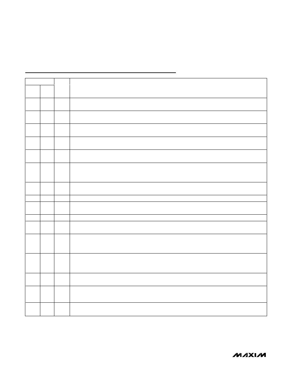
Pin Description (continued)
PIN
MAX
1586
MAX
1587
NAME
FUNCTION
35
29
SRAD
Serial Address Bit. SRAD allows the serial address of the MAX1586/MAX1587 to be changed in case it
conflicts with another serial device. If SRAD = GND, A1 = 0. If SRAD = IN, A1 = 1.
36
30
RSO
Open-Drain Reset Output. Deasserts when V7 exceeds 2.55V (typ rising). Has 65ms delay before release.
RSO is expected to connect to nRESET on the CPU.
37
31
MR
Manual Reset Input. A low input causes the RSO output to go low but impacts no other MAX1586/MAX1587
functions.
38
32
CC3
REG 3 Compensation Node. Connect a series resistor and capacitor from CC3 to GND to compensate the
regulation loop. See the Compensation and Stability section.
39
33
FB3
REG3 Feedback-Sense Input. Connect directly to the REG3 output voltage. Output voltage is set by the
serial interface.
40
—
ON6
On/Off Input for REG6. Drive high to turn on. When enabled, the REG6 output activates. ON6 has hysteresis
so an RC can be used to implement manual sequencing with respect to other inputs. It is expected that
ON1, ON2, and ON6 are connected to SYS_EN.
41
—
V6
Also known as VCC_USIM. Linear-regulator output. This voltage is programmable through the I
2
C™
interface to 0V, 1.8V, 2.5V, or 3.0V. The default voltage is 0V. REG6 is activated when ON6 is high.
42
—
IN6
Power Input to the V6 LDO. Typically connected to V1, but can also connect to IN.
43
36
PG1
REG1 Power Ground. Connect directly to a power-ground plane. Connect PG1, PG2, PG3, and GND
together at a single point as close to the IC as possible.
44
37
LX1
REG1 Switching Node. Connects to the REG1 inductor.
45
38
PV1
REG1 Power Input. Bypass to PG2 with a 4.7µF or greater low-ESR ceramic capacitor. PV1, PV2, PV3, and
IN must connect together externally.
46
35
ON1
On/Off Input for REG1. Drive high to turn on REG1. When enabled, the REG1 output soft-starts. ON1 has
hysteresis so an RC can be used to implement manual sequencing with respect to other inputs. It is
expected that ON1, ON2, and ON6 connect to SYS_EN.
47
39
SLP
Sleep Input. SLP selects which regulators ON1 and ON2 turn on. SLP = high is normal operation (ON1 and
ON2 are the enables for the V1 and V2 DC-DC converters). SLP = low is sleep operation (ON1 and ON2 are
the enables for the V1 and V2 LDOs).
48
—
DBI
Dual-Mode, Dead-Battery Input. Connect DBI to IN to set the dead-battery falling threshold to 3.15V (no
resistors needed). Connect DBI to a resistor-divider for an adjustable DBI threshold.
—
22
ON45
On/Off Input for REG4 and REG5. Drive high to turn on. When enabled, the REG4 and REG5 outputs
activate. ON45 has hysteresis so an RC can be used to implement manual sequencing with respect to
other inputs. It is expected that ON45 is connected to PWR_EN.
EP
EP
EP
Exposed Metal Pad. Connect the exposed pad to ground. Connecting the exposed pad to ground does not
remove the requirement for proper ground connections to the appropriate ground pins.
I
2
C is a trademark of Philips Corp. Purchase of I
2
C components
from Maxim Integrated Products, Inc. or one of its sublicensed
Associated Companies, conveys a license under the Philips
I
2
C Patent Rights to use these components in an I
2
C system,
provided that the system conforms to the I
2
C Standard
Specification as defined by Philips.