Definitions, Table 4. code table with v, 500v – Rainbow Electronics MAX1338 User Manual
Page 19: Table 5. input ranges, Table 6. lsb size with v
Definitions
Integral Nonlinearity (INL)
Integral nonlinearity is the deviation of the values on an
actual transfer function from a straight line. For these
devices, this straight line is a line drawn between the
endpoints of the transfer function, once offset and gain
errors have been nulled.
Differential Nonlinearity (DNL)
Differential nonlinearity is the difference between an
actual step width and the ideal value of 1 LSB. For
these devices, the DNL of each digital output code is
measured and the worst-case value is reported in the
Electrical Characteristics table. A DNL error specifica-
tion of less than ±1 LSB guarantees no missing codes
and a monotonic transfer function.
Offset Error
Offset error indicates how well the actual transfer func-
tion matches the ideal transfer function at a single point.
Typically, the point at which the offset error is specified
is at or near the zero scale of the transfer function or at
or near the midscale of the transfer function.
For the MAX1338, the ideal zero-scale digital output
transition from 0x3FFF to 0x0000 occurs with an analog
input voltage of zero. Offset error is the amount of ana-
log input-voltage deviation between the measured input
voltage and the calculated input voltage at the zero-
scale transition.
MAX1338
14-Bit, 4-Channel, Software-Programmable,
Multiranging, Simultaneous-Sampling ADC
______________________________________________________________________________________
19
INPUT VOLTAGE (V)
±10V INPUT
RANGE
SELECTED
±5V INPUT
RANGE
SELECTED
±2.5V INPUT
RANGE
SELECTED
±1.25V INPUT
RANGE
SELECTED
DECIMAL
EQUIVALENT
OUTPUT
(CODE
10
)
TWO’S COMPLEMENT
BINARY OUTPUT CODE
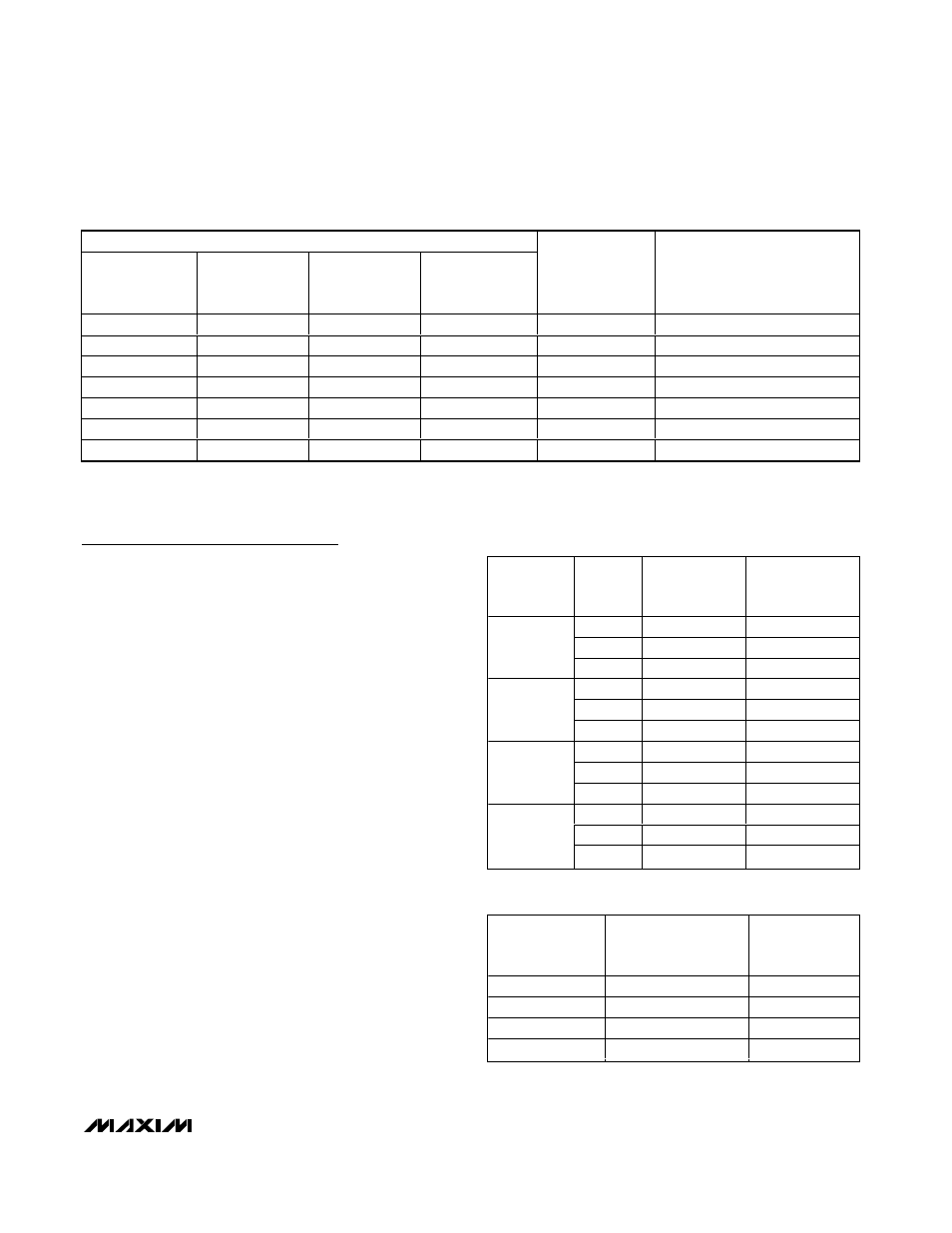
9.9988
4.9994
2.4998
1.2499
8191
01 1111 1111 1111
→
0x1FFF
9.9976
4.9988
2.4997
1.2498
8190
01 1111 1111 1110
→
0x1FFE
0.0012
0.0006
0.0002
0.0001
1
00 0000 0000 0001
→
0x0001
0
0
0
0
0
00 0000 0000 0000
→
0x0000
-0.0012
-0.0006
-0.0002
-0.0001
-1
11 1111 1111 1111
→
0x3FFF
-9.9988
-4.9994
-2.4998
-1.2499
-8191
10 0000 0000 0001
→
0x2001
-10.0000
-5.0000
-2.5000
-1.2500
-8192
10 0000 0000 0000
→
0x2000
Table 4. Code Table with V
REF
= 2.500V
SELECTED
INPUT
RANGE (V)
V
REFADC
(V)
FULL-SCALE
INPUT RANGE
(V)
ALLOWABLE
COMMON-MODE
RANGE (V)
2.0
±8
±5
2.5
±10
±5
±10
3.0
±12
±5
2.0
±4
±2.5
2.5
±5
±2.5
±5
3.0
±6
±2.5
2.0
±2
±1.25
2.5
±2.5
±1.25
±2.5
3.0
±3
±1.25
2.0
±1
±0.625
2.5
±1.25
±0.625
±1.25
3.0
±1.5
±0.625
Table 5. Input Ranges
SELECTED
INPUT RANGE
(V)
GAIN MULTIPLIER
(A)
LSB SIZE (mV)
±10
8
1.2207
±5
4
0.6104
±2.5
2
0.1526
±1.25
1
0.0736
Table 6. LSB Size with V
REF
= 2.500V