Max1338 – Rainbow Electronics MAX1338 User Manual
Page 16
MAX1338
Starting a Conversion
Internal Clock
For internal clock operation, force INTCLK/EXTCLK
high. To start a conversion using internal clock mode,
pull CONVST low for at least t
CONVST
. The T/H acquires
the signal while CONVST is low. An EOC signal pulses
low when the first result becomes available, and for
each subsequent result until the end of the conversion
cycle. The EOLC signal goes low when the last conver-
sion result becomes available (Figure 6).
External Clock
For external clock operation, force INTCLK/EXTCLK
low. To start a conversion using external clock mode,
pull CONVST low for at least t
CONVST
. The T/H circuits
track the input signal while CONVST is low. Conversion
begins on the rising edge of CONVST. Apply an exter-
nal clock to CLK. To avoid T/H droop degrading the
sampled analog input signals, the first CLK pulse must
occur within 10µs after the rising edge of CONVST and
have a minimum 1MHz clock frequency. The first con-
version result is available for read on the rising edge of
the 17th clock cycle, and subsequent conversions on
every 3rd clock cycle thereafter, as indicated by EOC
and EOLC.
Reading a Conversion Result
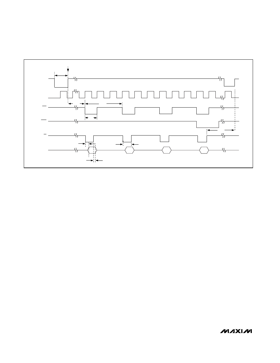
Reading During a Conversion
Figure 5 shows the interface signals to initiate a read
operation during a conversion cycle. CS can be held
low permanently, low during the RD cycles, or it can be
the same as RD. After initiating a conversion by bring-
ing CONVST high, wait for EOC to go low (about 3.4µs
in internal clock mode) or 17 clock cycles (external
clock mode) before reading the first conversion result.
Read the conversion result by bringing RD low, which
latches the data to the parallel digital output bus. Bring
RD high to release the digital bus. Wait for the next
falling edge of EOC (about 600ns in internal clock
mode or three clock cycles in external clock mode)
before reading the next result. When the last result is
available, EOLC goes low, along with EOC. Wait three
clock cycles, t
QUIET
, before starting the next conver-
sion cycle.
Reading After a Conversion
Figure 6 shows the interface signals for a read operation
after a conversion using an external clock. At the falling
of EOLC, on the 26th clock pulse after the initiation of a
conversion, driving CS and RD low places the first con-
version result onto the parallel I/O bus. Read the conver-
sion result on the rising edge of RD. Successive low
pulses of RD place the successive conversion results
14-Bit, 4-Channel, Software-Programmable,
Multiranging, Simultaneous-Sampling ADC
16
______________________________________________________________________________________
CONVST
17
18
19
20
21
22
23
24
25
26
27
29
t
QUIET
CH3
CH2
CH1
CH0
t
ACC
t
REQ
t
CONVST
SAMPLE
CLK
t
EOC1
t
NEXT
t
EOC
EOC
EOLC
RD
D0–D13
t
RDL
Figure 5. Reading During a Conversion—Internal or External Clock