Chip information, Functional diagram – Rainbow Electronics MAX1183 User Manual
Page 17
nents minus the fundamental, the first five harmonics,
and the DC offset.
Signal-to-Noise Plus Distortion (SINAD)
SINAD is computed by taking the ratio of the RMS sig-
nal to all spectral components minus the fundamental
and the DC offset.
Effective Number of Bits (ENOB)
ENOB specifies the dynamic performance of an ADC at
a specific input frequency and sampling rate. An ideal
ADC’s error consists of quantization noise only. ENOB
is computed from:
Total Harmonic Distortion (THD)
THD is typically the ratio of the RMS sum of the first four
harmonics of the input signal to the fundamental itself.
This is expressed as:
where V
1
is the fundamental amplitude, and V
2
through
V
5
are the amplitudes of the 2nd- through 5th-order
harmonics.
Spurious-Free Dynamic Range (SFDR)
SFDR is the ratio expressed in decibels of the RMS
amplitude of the fundamental (maximum signal compo-
nent) to the RMS value of the next-largest spurious
component, excluding DC offset.
Intermodulation Distortion (IMD)
The two-tone IMD is the ratio expressed in decibels of
either input tone to the worst 3rd-order (or higher) inter-
modulation products. The individual input tone levels
are at -6.5dB full scale and their envelope is at -0.5dB
full scale.
Chip Information
TRANSISTOR COUNT: 10,811
PROCESS: CMOS
THD
V
V
V
V
V
=
×
+
+
+
20
10
2
2
3
2
4
2
5
2
1
log
ENOB
SINAD
dB
dB
dB
=
−
(
)
1 76
6 02
.
.
MAX1183
Dual 10-Bit, 40Msps, +3V, Low-Power ADC with
Internal Reference and Parallel Outputs
______________________________________________________________________________________
17
GND
REFERENCE
OUTPUT
DRIVERS
CONTROL
T/H
T/H
PIPELINE
ADC
DEC
OUTPUT
DRIVERS
REFOUT
REFN COM REFP
REFIN
INA+
INA-
CLK
INB+
INB-
V
DD
DEC
PIPELINE
ADC
OGND
OV
DD
D9A–D0A
OE
D9B–D0B
T/B
PD
SLEEP
MAX1183
10
10
10
10
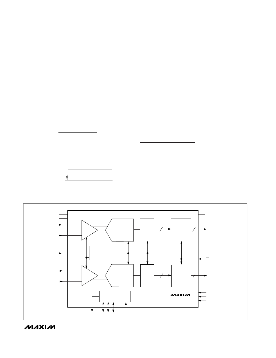
Functional Diagram