Rainbow Electronics MAX533 User Manual
Page 12
Interfacing to the Microprocessor
The MAX533 is Microwire™ and SPI™/QSPI™ compati-
ble. For SPI and QSPI, clear the CPOL and CPHA con-
figuration bits (CPOL = CPHA = 0). The SPI/QSPI CPOL
= CPHA = 1 configuration can also be used if the
DOUT output is ignored.
The MAX533 can interface with Intel’s 80C5X/80C3X
family in mode 0 if the SCLK clock polarity is inverted.
More universally, if a serial port is not available, three
lines from one of the parallel ports can be used for bit
manipulation.
Digital feedthrough at the voltage outputs is greatly
minimized by operating the serial clock only to update
the registers. Also see the Clock Feedthrough photo in
the
Typical Operating Characteristics section. The
clock idle state is low.
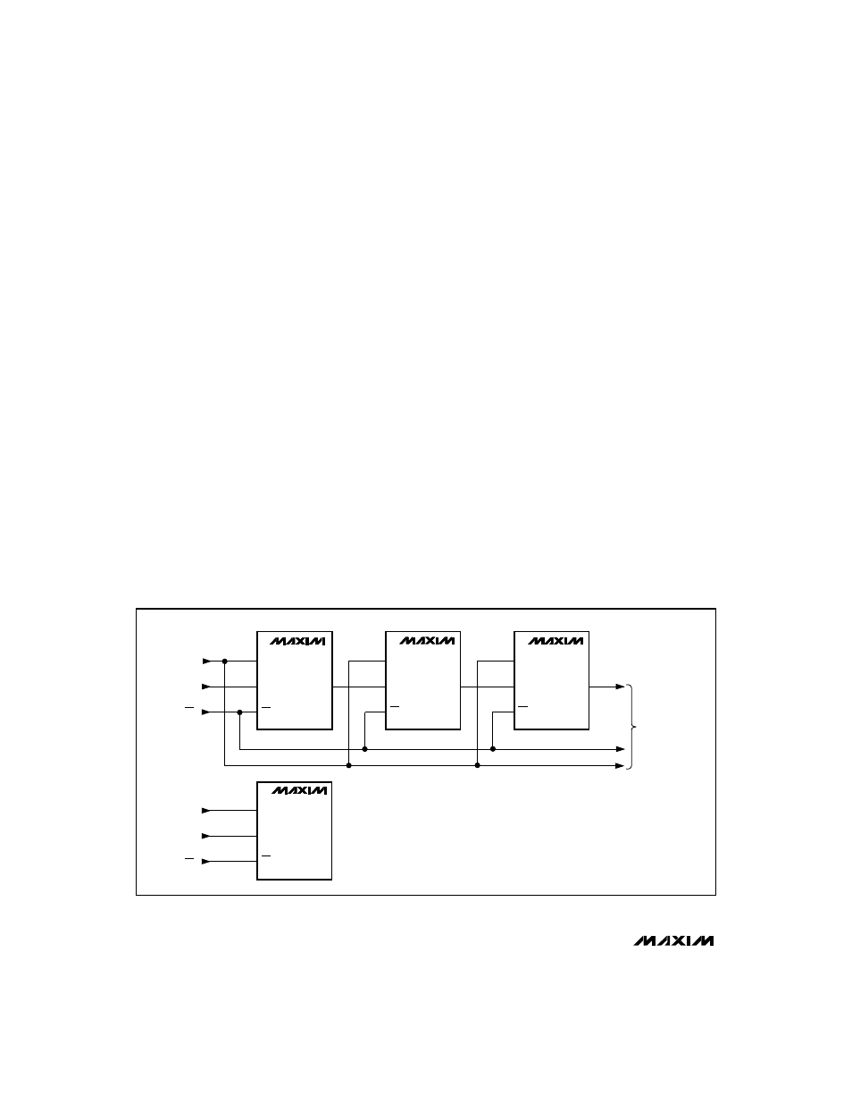
Daisy-Chaining Devices
Any number of MAX533s can be daisy-chained by con-
necting DOUT of one device to DIN of the following
device in the chain. The NOP instruction (Table 1)
allows data to be passed from DIN to DOUT without
changing the input or DAC registers of the passing
device. A 3-wire interface updates daisy-chained or
individual MAX533s simultaneously by bringing
CS
high (Figure 6).
Analog Section
DAC Operation
The MAX533 uses a matrix decoding architecture for
the DACs, which saves power in the overall system.
The external reference voltage is divided down by a
resistor string placed in a matrix fashion. Row and col-
umn decoders select the appropriate tab from the
resistor string to provide the needed analog voltages.
The resistor string presents a code-independent input
impedance to the reference and guarantees a mono-
tonic output. Figure 8 shows a simplified diagram of the
four DACs.
Reference Input
The voltage at REF sets the full-scale output voltage for
all four DACs. The 460k
Ω
typical input impedance at
REF is code independent. The output voltage for any
DAC can be represented by a digitally programmable
voltage source as follows:
V
OUT
= (NB x V
REF
) / 256
where NB is the numerical value of the DAC’s binary
input code.
MAX533
2.7V, Low-Power, 8-Bit Quad DAC
with Rail-to-Rail Output Buffers
12
______________________________________________________________________________________
SCLK
DIN
DEVICE A
DEVICE B
DEVICE C
CS
MAX533
SCLK
DIN
CS
MAX533
SCLK
DIN
CS
MAX533
SCLK
DIN
CS
MAX533
DOUT
DOUT
DOUT
SCLK
DIN
CS
SCLK
DIN
CS
TO OTHER
SERIAL DEVICES
Figure 6. Daisy-chained or individual MAX533s are simultaneously updated by bringing
CS high. Only three wires are required.
SPI and QSPI are trademarks of Motorola, Inc. Microwire is a trademark of National Semiconductor Corp.