Rainbow Electronics MAX1567 User Manual
Page 8
MAX1566/MAX1567
Six-Channel, High-Efficiency, Digital
Camera Power Supplies
8
_______________________________________________________________________________________
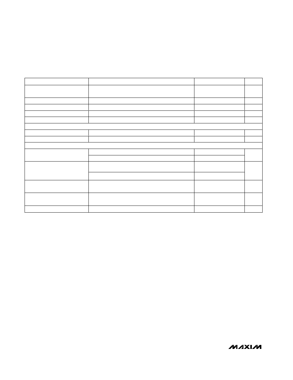
ELECTRICAL CHARACTERISTICS (continued)
(V
PVSU
= V
PV
= V
PVM
= V
PVSD
= V
INDL2
= 3.6V, T
A
= -40°C to +85°C, unless otherwise noted.)
PARAMETER
CONDITIONS
MIN
MAX
UNITS
AUX3 FBL or FBH to CC
Transconductance
35
150
µS
FB_ Input Leakage Current
-100
+100
nA
DL_ Driver Resistance
Output high or low
7
Ω
AUX1OK Output Low
0.1mA into
AUX1OK
0.1
V
AUX1OK Leakage Current
ONSU = GND
1
µA
OVERLOAD PROTECTION
SCF Leakage Current
ONSU = PVSU, FBSU = 1.5V
1
µA
SCF Output Low Voltage
0.1mA into SCF
0.1
V
LOGIC INPUTS (ON_, SUSD)
1.1V < PVSU < 1.8V
0.2
ONSU Input Low Level
1.8V < PVSU < 5.5V
0.4
v
1.1V < PVSU < 1.8V
(PVSU
- 0.2)
ONSU Input High Level
1.8V < PVSU < 5.5V
1.6
V
ONM, ONSD, ON1, ON2, ON3,
SUSD Input Low Level
2.7V < PVSU < 5.5V (Note 8)
0.4
V
ONM, ONSD, ON1, ON2, ON3,
SUSD Input High Level
2.7V < PVSU < 5.5V (Note 8)
1.6
V
SUSD Input Leakage
1
µA
Note 2: The MAX1566/MAX1567 are powered from the step-up output (PVSU). An internal low-voltage startup oscillator drives the
step-up starting at approximately 0.9V until PVSU reaches approximately 2.5V. When PVSU reaches 2.5V, the main control
circuitry takes over. Once the step-up is up and running, it can maintain operation with very low input voltages; however,
output current is limited.
Note 3: Since the device is powered from PVSU, a Schottky rectifier, connected from the battery to PVSU, is required for low-voltage
startup.
Note 4: The step-up regulator is in startup mode until this voltage is reached. Do not apply full load current during startup. A power-
OK output can be used with an external PFET to gate the load until the step-up is in regulation. See the
AUX1OK
,
SDOK
,
and SCF Connections section.
Note 5: The step-up current limit in startup refers to the LXSU switch current limit, not the output current limit.
Note 6: If the main converter is configured as a step-up (SUSD = PVSU), the P-channel synchronous rectifier is disabled until the
2.5V normal operation threshold has been exceeded. If the main converter is configured as a step-down (SUSD = GND), all
step-down operation is locked out until the normal operation threshold has been exceeded. When the main is configured as
a step-down, operation in dropout (100% duty cycle) can only be maintained for 100,000 OSC cycles before the output is
considered faulted, triggering global shutdown.
Note 7: Operation in dropout (100% duty cycle) can only be maintained for 100,000 OSC cycles before the output is considered
faulted, triggering global shutdown.
Note 8: ONM, ONSD, ON1, ON2, and ON3 are disabled until 1024 OSC cycles after PVSU reaches 2.7V.