Pin description – Rainbow Electronics MAX1567 User Manual
Page 12
MAX1566/MAX1567
Six-Channel, High-Efficiency, Digital
Camera Power Supplies
12
______________________________________________________________________________________
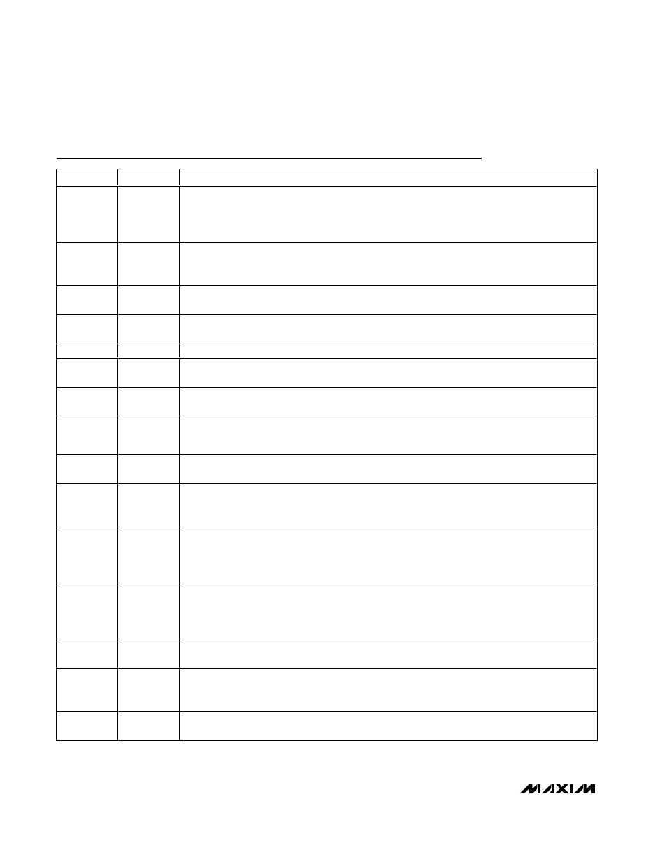
Pin Description
PIN
NAME
FUNCTION
1
FB3H
AUX3 Controller Voltage Feedback Input. Connect a resistive voltage-divider from the step-up
converter output to FBH to set the output voltage. The feedback threshold is 1.25V. This pin is high
impedance in shutdown. FB3H can provide conventional voltage feedback (with FB3L grounded) or
open-LED protection in white LED drive circuits.
2
CC1
AUX1 Controller Compensation Node. Connect a series resistor-capacitor from this pin to GND to
compensate the converter control loop. This pin is actively driven to GND in shutdown, overload, and
thermal limit. See the AUX Compensation section.
3
FB1
AUX1 Controller Feedback Input. The feedback threshold is 1.25V. This pin is high impedance in
shutdown.
4
ON1
AUX1 Controller On/Off Input. Logic high = on; however, turn-on is locked out until 1024 OSC cycles
after the step-up has reached regulation. This pin has an internal 330k
Ω pulldown resistance to GND.
5
PGSD
Power Ground. Connect all PG_ pins to GND with short wide traces as close to the IC as possible.
6
LXSD
Step-Down Converter Switching Node. Connect to the inductor of the step-down converter. LXSD is
high impedance in shutdown.
7
PVSD
Step-Down Converter Input. Bypass to GND with a 1µF ceramic capacitor. The step-down efficiency
is measured from this input.
8
ONSD
Step-Down Converter On/Off Control Input. Logic high = on; however, turn-on is locked out until 1024
OSC cycles after the step-up has reached regulation. This pin has an internal 330k
Ω pulldown
resistance to GND.
9
FBSD
Step-Down Converter Feedback Input. The feedback threshold is 1.25V. This pin is high impedance
in shutdown.
10
CCSD
Step-Down Converter Compensation Node. Connect a series resistor-capacitor from this pin to GND
for compensating the converter control loop. This pin is actively driven to GND in shutdown, overload,
and thermal limit. See the Step-Down Compensation section.
11
SUSD
Configures the Main Converter as a Step-Up or a Step-Down. This function must be hardwired. On-
the-fly changes are not allowed. With SUSD connected to PV, the main is configured as a step-up
and PVM is the converter output. With SUSD connected to GND, the main is configured as a step-
down and PVM is the power input.
12
CCM
Main Converter Compensation Node. Connect a series resistor-capacitor from this pin to GND for
compensating the converter control loop. This pin is actively driven to GND in shutdown, overload,
and thermal limit. See the Step-Up Compensation section when the main is used in step-up mode
and the Step-Down Compensation section when the main is used in step-down mode.
13
FBM
Main Converter Feedback Input. The feedback threshold is 1.25V. This pin is high impedance in
shutdown. The main output voltage must not be set higher than the step-up output.
14
ONM
On/Off Control for the Main DC-to-DC Converter. Logic high = on; however, turn-on is locked out until
1024 OSC cycles after the step-up has reached regulation. This pin has an internal 330k
Ω pulldown
resistance to GND. SUSD pin configures the main converter as a step-up or step-down.
15
REF
Reference Output. Bypass REF to GND with a 0.1µF or greater capacitor. The maximum-allowed REF
load is 200µA. REF is actively pulled to GND when the step-up is shut down (all converters turn off).