Pin description (continued) – Rainbow Electronics MAX1567 User Manual
Page 13
MAX1566/MAX1567
Six-Channel, High-Efficiency, Digital
Camera Power Supplies
______________________________________________________________________________________
13
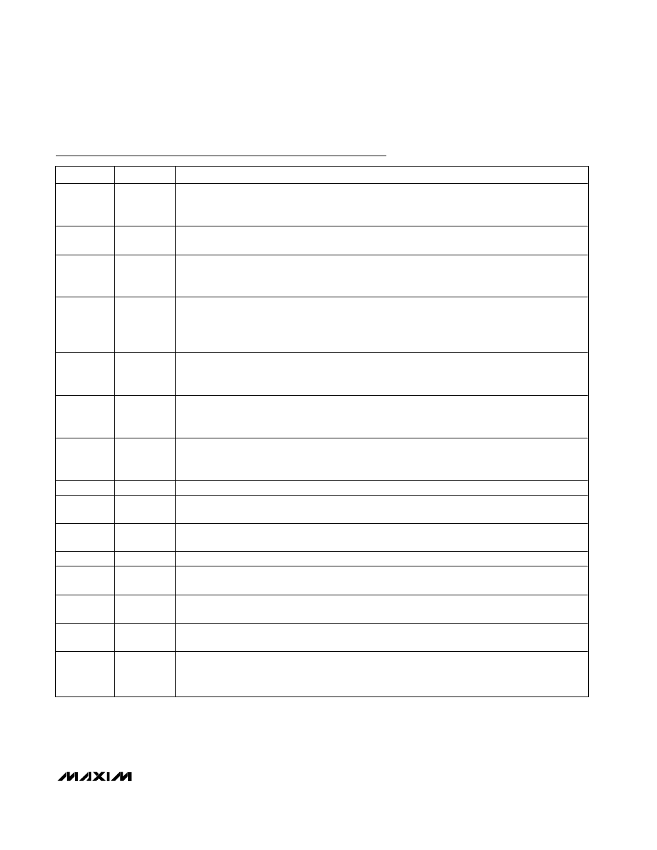
Pin Description (continued)
PIN
NAME
FUNCTION
16
CCSU
Step-Up Converter Compensation Node. Connect a series resistor-capacitor from this pin to GND for
compensating the converter control loop. This pin is actively driven to GND in shutdown, overload,
and thermal limit. See the Step-Up Compensation section.
17
FBSU
Step-Up Converter Feedback Input. The feedback threshold is 1.25V. This pin is high impedance in
shutdown.
18
ONSU
Step-Up Converter On/Off Control. Logic high = on. All other ON_ pins are locked out until 1024 OSC
cycles after the step-up DC-to-DC converter output has reached its final value. This pin has an
internal 330k
Ω pulldown resistance to GND.
19
SCF
Open-Drain, Active-Low, Short-Circuit Flag Output. SCF goes open when overload protection occurs
and during startup. SCF can drive high-side PFET switches connected to one or more outputs to
completely disconnect the load when the channel turns off in response to a logic command or an
overload. See the Status Outputs (
SDOK
,
AUX1OK
, SCF) section.
20
AUX1OK
Open-Drain, Active-Low, Power-OK Signal for AUX1 Controller.
AUX1OK goes low when the AUX1
controller has successfully completed soft-start.
AUX1OK goes high impedance in shutdown,
overload, and thermal limit.
21
SDOK
Open-Drain, Active-Low, Power-OK Signal for Step-Down Converter.
SDOK goes low when the step-
down has successfully completed soft-start.
SDOK goes high impedance in shutdown, overload, and
thermal limit.
22
OSC
Oscillator Control. Connect a timing capacitor from OSC to GND and a timing resistor from OSC to
PVSU (or other DC voltage) to set the oscillator frequency between 100kHz and 1MHz. See the
Setting the Switching Frequency section. This pin is high impedance in shutdown.
23
PGSU
Power Ground. Connect all PG_ pins to GND with short wide traces as close to the IC as possible.
24
LXSU
Step-Up Converter Switching Node. Connect to the inductor of the step-up converter. LXSU is high
impedance in shutdown.
25
PVSU
Power Output of the Step-Up DC-to-DC Converter. PVSU can also power other converter channels.
Connect PVSU and PV together.
26
PGM
Power Ground. Connect all PG_ pins to GND with short wide traces as close to the IC as possible.
27
LXM
Main Converter Switching Node. Connect to the inductor of the main converter (can be configured as
a step-up or step-down by SUSD). LXM is high impedance in shutdown.
28
PVM
When SUSD = PVSU, the main converter is configured as a step-up and PVM is the main output.
When SUSD = GND, the main is configured as a step-down and PVM is the power input.
29
ON2
AUX2 Controller On/Off Input. Logic high = on; however, turn-on is locked out until 1024 OSC cycles
after the step-up has reached regulation. This pin has an internal 330k
Ω pulldown resistance to GND.
30
CC2
AUX2 Controller Compensation Node. Connect a series resistor-capacitor from this pin to GND to
compensate the converter control loop. This pin is actively driven to GND in shutdown, overload, and
thermal limit. See the AUX Compensation section.