Rainbow Electronics MAX1567 User Manual
Page 25
MAX1566/MAX1567
Six-Channel, High-Efficiency, Digital
Camera Power Supplies
______________________________________________________________________________________
25
Soft-Start
The MAX1566/MAX1567 channels feature a soft-start
function that limits inrush current and prevents exces-
sive battery loading at startup by ramping the output
voltage of each channel up to the regulation voltage.
This is accomplished by ramping the internal reference
inputs to each channel error amplifier from 0V to the
1.25V reference voltage over a period of 4096 oscillator
cycles (16ms at 500kHz) when initial power is applied
or when a channel is enabled.
The step-down soft-start ramp takes half the time (2048
clock cycles) of the other channel ramps. This allows
the step-down and main outputs to track each other
and rise at nearly the same dV/dt rate on power-up.
Once the step-down output reaches its regulation point
(1.5V or 1.8V typ), the main output (3.3V typ) continues
to rise at the same ramp rate. See the Typical
Operating Characteristics Main and Step-Down Startup
Waveforms graphs.
Soft-start is not included in the step-up converter to
avoid limiting startup capability with loading.
Fault Protection
The MAX1566/MAX1567 have robust fault and overload
protection. After power-up, the device is set to detect
an out-of-regulation state that could be caused by an
overload or short. If any DC-to-DC converter channel
(step-up, main, step-down, or any of the auxiliary con-
trollers) remains faulted for 100,000 clock cycles
(200ms at 500kHz), then all outputs latch off until the
step-up DC-to-DC converter is reinitialized by the
ONSU pin or by cycling the input power. The fault-
detection circuitry for any channel is disabled during its
initial turn-on soft-start sequence.
An exception to the standard fault behavior is that there
is no 100,000 clock cycle delay in entering the fault
state if the step-up output (PVSU) is dragged below its
2.5V UVLO threshold or is shorted. In this case, the
MAX1566
MAX1567
(PARTIAL)
AUX1OK
CURRENT-
MODE
STEP-UP
PWM
PVSU
PV
LXSU
L2
PGSU
FBSU
V
SU
+5V
GATED +5V
TO CCD
TO
V
BATT
TO
V
BATT
DL1
FB1
PVSU
AUX1
PWM
15V
100mA
D6
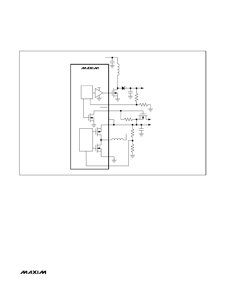
Figure 16.
AUX1OK
Drives an External PFET that Gates 5V Supply to the CCD After the +15V CCD Bias Supply Is Up