Sdok, Aux1ok, Master-slave configurations – Rainbow Electronics MAX1567 User Manual
Page 22: Status outputs, Scf)
MAX1566/MAX1567
Six-Channel, High-Efficiency, Digital
Camera Power Supplies
22
______________________________________________________________________________________
Master-Slave Configurations
The MAX1566/MAX1567 support MAX1801 slave PWM
controllers that obtain input power, a voltage reference,
and an oscillator signal directly from the MAX1566/
MAX1567 master. The master-slave configuration allows
channels to be easily added and minimizes system cost
by eliminating redundant circuitry. The slaves also con-
trol the harmonic content of noise because their operat-
ing frequency is synchronized to that of the MAX1566/
MAX1567 master converter. A MAX1801 connection to
the MAX1566/MAX1567 is shown in Figure 14.
Status Outputs (
SDOK
,
AUX1OK
, SCF)
The MAX1566/MAX1567 include three versatile status
outputs that can provide information to the system. All
are open-drain outputs and can directly drive MOSFET
switches to facilitate sequencing, disconnect loads
during overloads, or perform other hardware-based
functions.
C
OSC
V
REF
(1.25V)
V
SU
R
OSC
OSC
150ns
ONE-SHOT
MAX1566
MAX1567
Figure 6. Oscillator Functional Diagram
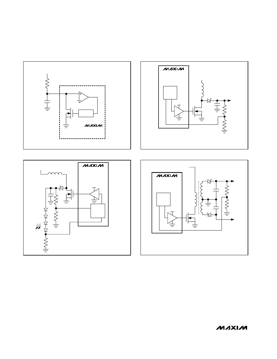
FB3L
(0.2V)
FB3H
(1.25V)
DL3
PVSU
AUX3
PWM
D2–D5
LEDS
R2
R1
R3
MAX1566
MAX1567
(PARTIAL)
TO
V
BATT
NOTE: IF OPEN LED PROTECTION IS NOT
REQUIRED, REMOVE R2 AND R3 AND GROUND FB3H.
Figure 7. LED drive with open LED overvoltage protection is
provided by the additional feedback input to AUX3, FB3H.
DL_
FB_
PVSU
AUX
PWM
+15V
50mA
LCD
D6
Q1
TO
V
BATT
MAX1566
MAX1567
(PARTIAL)
NOTE: THIS CIRCUIT CAN OPERATE WITH AUX1, AUX2,
OR AUX3 ON THE MAX1566, AND WITH AUX1 OR AUX3 ON
THE MAX1567. TO USE AUX3, FB3L = GND, AND
FB3H IS USED FOR FEEDBACK.
Figure 8. +15V LCD Bias with Basic Boost Topology
DL_
FB_
PVSU
AUX
PWM
+15V
50mA
CCD+
-7.5V
30mA
CCD-
D2
Q1
TO
V
BATT
MAX1566
MAX1567
(PARTIAL)
NOTE: THIS CIRCUIT CAN OPERATE WITH AUX1, AUX2,
OR AUX3 ON THE MAX1566, AND WITH AUX1 OR AUX3 ON
THE MAX1567. TO USE AUX3, FB3L = GND, AND
FB3H IS USED FOR FEEDBACK.
Figure 9. +15V and -7.5V CCD Bias with Transformer