Rainbow Electronics MAX1567 User Manual
Page 23
MAX1566/MAX1567
Six-Channel, High-Efficiency, Digital
Camera Power Supplies
______________________________________________________________________________________
23
SDOK pulls low when the step-down has successfully
completed soft-start. SDOK goes high impedance in
shutdown, overload, and thermal limit. A typical use for
SDOK is to drive a P-channel MOSFET that connects
3.3V power to the CPU I/O after the CPU core is pow-
ered up (Figure 15), thus providing safe sequencing in
hardware without system intervention.
A
AU
UX
X1
1O
OK
K pulls low when the AUX1 controller has suc-
cessfully completed soft-start. AUX1OK goes high
impedance in shutdown, overload, and thermal limit. A
typical use for AUX1OK is to drive a P-channel MOSFET
that connects 5V power to the CCD after the 15V CCD
bias (generated by AUX1) is powered up (Figure 16).
SCF goes high (high impedance, open drain) when
overload protection occurs. Under normal operation,
SCF pulls low. SCF can drive a high-side P-channel
MOSFET switch that can disconnect a load during
power-up or when a channel turns off in response to a
logic command or an overload. Several connections
are possible for SCF. One is shown in Figure 17 where
SCF provides load disconnect for the step-up on fault
and power-up.
DL2
FB2
REF
AUX2
INVERTING
PWM
INDL2
-7.5V
100mA
TO V
BATT
R
TOP
R
REF
MAX1567
(PARTIAL)
Figure 10. Regulated -7.5V Negative CCD (Bias is provided by
conventional inverter (works only with the MAX1567).)
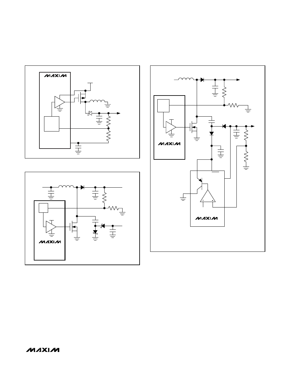
MAX1566
MAX1567
(PARTIAL)
AUX_
PWM
PVSU
DL_
FB_
C2
1
µF
TO V
BATT
1
µF
L1
10
µH
D2
R1
1M
Ω
R2
90.9k
Ω
C1
1
µF
D3
D1
Q1
C3
1
µF
V
OUT+
+15V
20mA
V
OUT-
-15V
10mA
Figure 11. ±15V Output Using an AUX-Driven Boost with
Charge-Pump Inversion
MAX1566/MAX1567
(PARTIAL)
AUX_
PWM
PVSU
DL_
FB_
TO V
BATT
MAX1616
FB_
GND
SHDN
IN
OUT
+1.25V
+15V
20mA
-7.5V
20mA
NOTE: THIS CIRCUIT CAN OPERATE WITH AUX1, AUX2, OR AUX3 ON THE MAX1566,
AND WITH AUX1 OR AUX3 ON THE MAX1567. TO USE AUX3, FB3L = GND,
AND FB3H IS USED FOR FEEDBACK.
Figure 12. +15V and -7.5V CCD Bias Without Transformer
Using Boost with a Diode-Capacitor Charge Pump (A positive-
output linear regulator (MAX1616) can be used to regulate the
negative output of the charge pump.)