Reference, Oscillator, Low-voltage startup oscillator – Rainbow Electronics MAX1567 User Manual
Page 26
MAX1566/MAX1567
Six-Channel, High-Efficiency, Digital
Camera Power Supplies
26
______________________________________________________________________________________
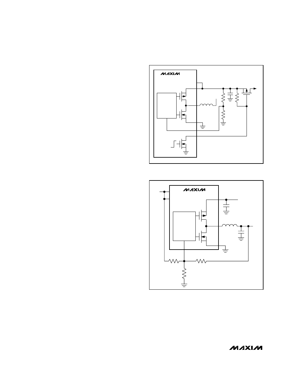
step-up UVLO immediately triggers and shuts down all
channels. The step-up then continues to attempt start-
ing. If the step-up output short remains, these attempts
cannot succeed since PVSU remains near ground.
If a soft-short or overload remains on PVSU, the startup
oscillator switches the internal N-channel MOSFET, but
fault is retriggered if regulation is not achieved by the
end of the soft-start interval. If PVSU is dragged below
the input, the overload is supplied by the body diode of
the internal synchronous rectifier, or by a Schottky
diode connected from the battery to PVSU. If desired,
this overload current can be interrupted by a P-channel
MOSFET controlled by SCF, as shown in Figure 17.
Reference
The MAX1566/MAX1567 has a precise 1.250V refer-
ence. Connect a 0.1µF ceramic bypass capacitor from
REF to GND within 0.2in (5mm) of the REF pin. REF can
source up to 200µA and is enabled whenever ONSU is
high and PVSU is above 2.5V. The auxiliary controllers
and MAX1801 slave controllers (if connected) each sink
up to 30µA REF current during startup. In addition, the
feedback network for the AUX2 inverter (MAX1567) also
draws current from REF. If the 200µA REF load limit
must be exceeded, buffer REF with an external op amp.
Oscillator
All DC-to-DC converter channels employ fixed-frequency
PWM operation. The operating frequency is set by an RC
network at the OSC pin. The range of usable settings is
100kHz to 1MHz. When MAX1801 slave controllers are
added, they operate at the frequency set by OSC.
The oscillator uses a comparator, a 150ns one-shot, and
an internal NFET switch in conjunction with an external
timing resistor and capacitor (Figure 6). When the switch
is open, the capacitor voltage exponentially approaches
the step-up output voltage from zero with a time constant
given by the product of R
OSC
and C
OSC
. The compara-
tor output switches high when the capacitor voltage
reaches V
REF
(1.25V). In turn, the one-shot activates the
internal MOSFET switch to discharge the capacitor for
150ns, and the cycle repeats. The oscillation frequency
changes as the main output voltage ramps upward fol-
lowing startup. The oscillation frequency is then constant
once the main output is in regulation.
Low-Voltage Startup Oscillator
The MAX1566/MAX1567 internal control and reference-
voltage circuitry receive power from PVSU and do not
function when PVSU is less than 2.5V. To ensure low-
voltage startup, the step-up employs a low-voltage
startup oscillator that activates at 0.9V if a Schottky rec-
tifier is connected from V
BATT
to PVSU (1.1V with no
Schottky rectifier). The startup oscillator drives the inter-
nal N-channel MOSFET at LXSU until PVSU reaches
2.5V, at which point voltage control is passed to the
current-mode PWM circuitry.
Once in regulation, the MAX1566/MAX1567 operate
with inputs as low as 0.7V since internal power for the
IC is supplied by PVSU. At low input voltages, the step-
CURRENT-MODE
STEP-UP
PWM
PVSU
PV
LXSU
L2
PGSU
MAX1566
MAX1567
(PARTIAL)
FBSD
SCF
OK
PWR ON
OR FAULT
V
SU
+5V
TO
V
BATT
Figure 17. SCF Drives PFET Load Switch on 5V to Disconnect
Load on Fault and Allow Full-Load Startup
CURRENT-MODE
STEP-DOWN
PVSD
LXSD
4.7
µH
22
µF
10
µF
PGSD
MAX1566
MAX1567
(PARTIAL)
PVSU
PV
R1
56k
Ω
R3
100k
Ω
R2
100k
Ω
FBSD
V
FBSD
1.25V
V
SU
3.3V
V
SD
0.8V
Figure 18. Setting PVSD for Outputs Below 1.25V