Max1800 digital camera step-up power supply – Rainbow Electronics MAX1800 User Manual
Page 21
Choose the MOSFET for low dropout. The maximum
acceptable on-resistance of the MOSFET is determined
by the maximum load current to achieve the required
dropout voltage (minimum input voltage minus output
voltage):
Determine the minimum output capacitance as follows.
The output capacitor and load resistance set the domi-
nant pole (f
P1
):
The second pole (f
P2
) occurs due to the AO output
resistance and the gate capacitance of the external
MOSFET:
where R
AO
is the output resistance of the gain block at
AO, and C
(GATE-Q1)
is the total gate capacitance of the
MOSFET, Q1. The control loop DC gain is:
where A
V-GB
is the voltage gain from AI to AO (typically
100), and G
(FS-Q1)
is the forward transconductance
gain of Q1. Choose the output capacitance so that the
second pole occurs at or above the loop-gain crossover
frequency:
Since V
REF
is 1.25V, A
(V-GB)
is typically 100, and R
AO
is typically 800
Ω, then:
Using the Linear Regulator to Make a
Step-Up/Step-Down Circuit
Some applications have a battery voltage that can be
either greater than or less than the desired output volt-
age. In this case, a step-up or step-down converter will
not be able to generate the required output voltage
under all conditions. To avoid this limitation, use a step-
C
G
C
V
OUT
FS Q
GATE Q
OUT
≥
−
(
)
−
(
)
,
12 500
1
1
C
V
V
A
G
R
C
OUT
REF
OUT
V GB
FS Q
AO
GATE Q
≥
−
(
)
−
(
)
−
(
)
1
1
A
V
V
A
G
R
VLOOP
REF
OUT
V GB
FS Q
LOAD
=
−
(
)
−
(
)
1
f
R
C
P
AO
GATE Q
2
1
1
2
(
)
=
−
π
f
R
C
P
LOAD
OUT
1
1
2
=
π
R
DS ON
−
≤
V
I
DROPOUT
LOAD(MAX)
R
R
V
V
OUT
REF
1
2
1
=
−
MAX1800
Digital Camera Step-Up
Power Supply
______________________________________________________________________________________
21
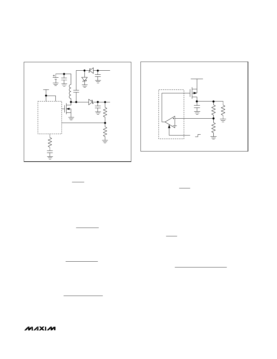
Figure 11. Linear Regulator
C
OUT
Q
1
V
REF
R
1
R
2
LOAD
RESISTOR
(R
L
)
INPUT VOLTAGE
(FROM MAIN
OUTPUT)
PART OF MAX 1800
ONA
AI
AI
ON
OFF
Q
1
C
1
C
2
C
3
D
1
D
2
D
3
C
C
R
1
V
OUT+
V
OUT-
L
R
2
R
C
MAIN
IN
COMP
DCON
PART OF
MAX1800
DL
FB
INPUT
1-CELL
LITHIUM-ION
Figure 10. Auxiliary Charge-Pump Configuration