Max1800 digital camera step-up power supply – Rainbow Electronics MAX1800 User Manual
Page 17
MAX1800
Digital Camera Step-Up
Power Supply
______________________________________________________________________________________
17
Auxiliary Controllers
The auxiliary controllers use voltage mode to regulate
their output voltages, so the control-loop compensation
is slightly more complex than that for the main convert-
er. Use one of the two following procedures:
Discontinuous Inductor Current
For discontinuous inductor current, the PWM converter
has a single pole. The pole frequency and DC gain of
the PWM controller are dependent on the operating
duty cycle, which is:
where R
E
is the equivalent load resistance, or:
The frequency of the single pole due to the PWM con-
verter is:
The DC gain of the PWM controller is:
Note that the pole frequency decreases and the DC
gain increases proportionally as the load resistance
(R
LOAD
) is increased. Since the crossover frequency is
the product of the pole frequency and the DC gain, it
remains independent of the load.
The gain through the voltage-divider is:
The DC gain of the error amplifier is A
VEA
= 2000V/V.
Thus, the DC loop gain is:
A
VDC
= A
VDV
A
VEA
A
VO
The compensation resistor-capacitor pair at COMP
cause a pole and zero at frequencies (in Hz):
The equivalent series resistance (ESR) of the output fil-
ter capacitor causes a zero in the loop response at the
frequency (in Hz):
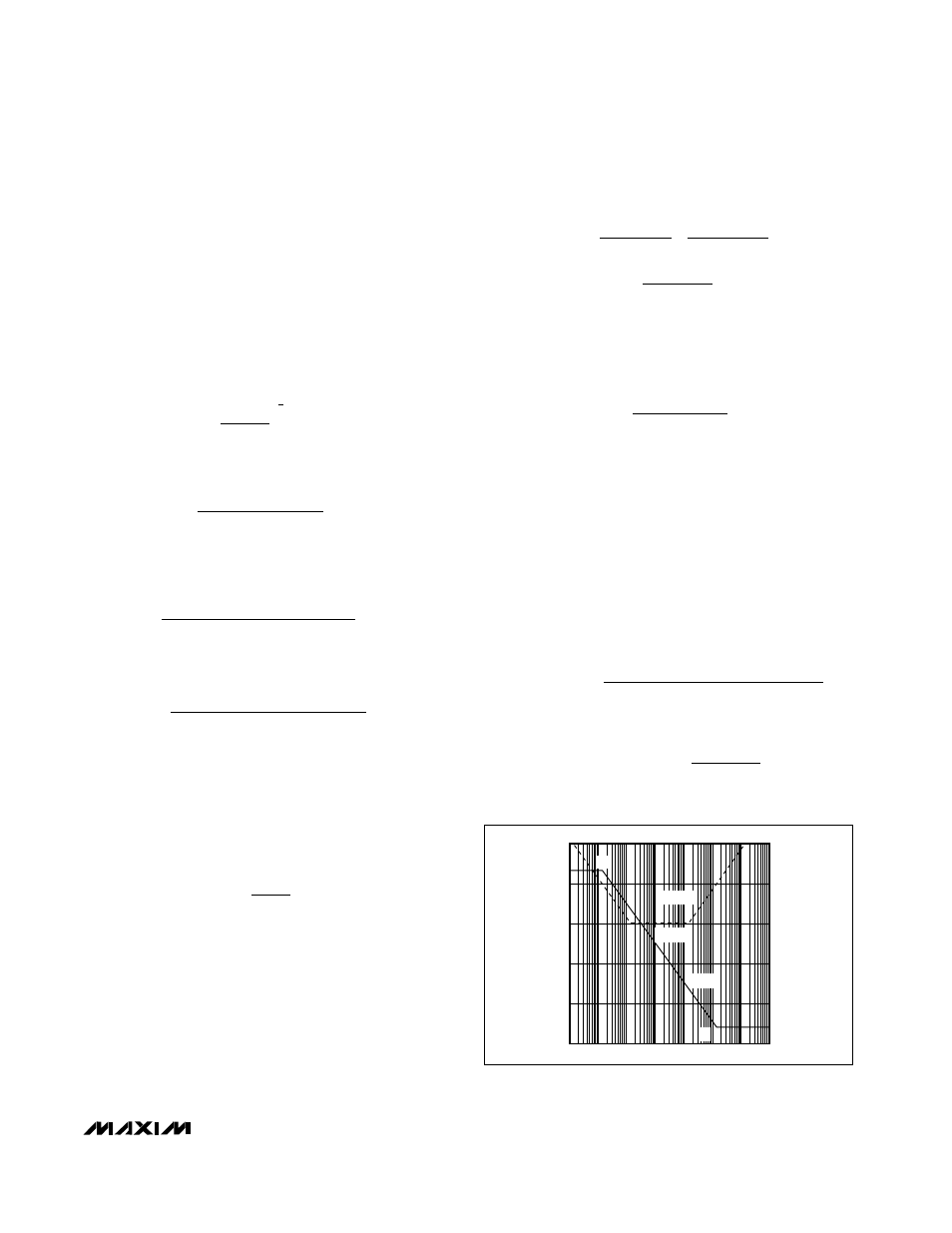
The DC gain, and the poles and zeros are shown in the
Bode plot of Figure 6.
To achieve a stable circuit with the Bode plot of Figure
6, perform the following procedure:
1) Choose the compensation resistor R
C
that is equiv-
alent to the inverse of the transconductance of the
error amplifier, 1/ R
C
= G
EA
= 100µS, or R
C
= 10k
Ω.
This sets the high-frequency voltage gain of the
error amplifier to 0dB.
2) Determine the maximum output pole frequency:
where:
R
LOAD(MIN)
OUT
OUT(MAX)
V
I
=
P
2(V
- V
V
- V
C
O(MAX)
OUT
IN)
OUT
IN
LOAD(MIN)
OUT
=
2
π(
) R
Z
C
ESR
O
OUT
=
1
2
π
P
G
C
C
Z
R C
C
EA
C
C
C
C
C
=
=
×
=
4000
1
4 10
1
2
7
π
π
π
A
V
V
VDV
REF
OUT
=
A
V
V
V
V
V
R
C
VO
OUT
OUT
IN
OUT
IN
LOAD
OUT
=
−
−
(
)
2
2
(
)
π
P
V
V
V
V
R
C
O
OUT
IN
OUT
IN
LOAD
OUT
=
−
(
)
−
(
)
2
2
π
R
V
R
V
V
V
E
IN
LOAD
OUT
OUT
IN
=
−
(
)
2
D
Lf
R
OSC
E
=
2
1
2
FREQUENCY
A
VDC
GAIN
(dB)
PHASE
180
°
90
°
0
°
O
-20
80
60
40
20
PHASE
GAIN
Z
C
= P
O
P
C
Z
O
Figure 6. MAX1800 Discontinuous-Current, Voltage-Mode,
Step-Up Converter Bode Plot