Max1800 digital camera step-up power supply – Rainbow Electronics MAX1800 User Manual
Page 12
MAX1800
Digital Camera Step-Up
Power Supply
12
______________________________________________________________________________________
Analog Gain Block
The MAX1800 analog gain block is a voltage amplifier
with a gain of 100 and a push-pull output stage with
2.5mA drive capability. The analog gain block can be
used with an external P-channel MOSFET pass transis-
tor to build a low-dropout linear regulator or can func-
tion as a comparator.
Reference
The MAX1800 has an internal 1.250V, 1.6% bandgap
reference. Connect a 0.1µF bypass capacitor from REF
to GND within 0.2in (5mm) of the REF pin. REF can
source up to 200µA of external load current, and it is
enabled whenever ONM is high and V
OUT
is above the
main undervoltage lockout threshold. The internal ana-
log gain block, auxiliary controllers, and MAX1801
slave controllers each sink up to 30µA REF current dur-
ing startup. If multiple MAX1801 slave controllers are
turned on simultaneously, ensure that the master volt-
age reference can provide sufficient current or buffer
the reference with an appropriate unity-gain amplifier.
Oscillator
The oscillator uses a comparator, a 100ns one-shot,
and an internal N-channel MOSFET switch in conjunc-
tion with an external timing resistor and capacitor to
generate the oscillator signal at OSC (Figure 4). The
capacitor voltage exponentially approaches the main
output voltage from zero with a time constant given by
the R
OSC
C
OSC
product when the switch is open, and
the comparator output becomes high when the capaci-
tor voltage reaches V
REF
(1.25V). In turn, the one-shot
activates the internal MOSFET switch to discharge the
capacitor within a 100ns interval, and the cycle
repeats. Note that the oscillation frequency changes as
the main output voltage ramps upward following start-
up. The oscillation frequency is constant while the main
output is in regulation.
Low-Voltage Startup Oscillator
The MAX1800 internal control and reference-voltage
circuitry receive power from the main output and do not
function when the main output voltage is less than the
main undervoltage lockout threshold. The MAX1800
main controller uses a low-voltage startup oscillator,
allowing it to start from an input voltage as low as 0.9V.
At startup, the low-voltage oscillator switches the inter-
nal LX-connected N-channel MOSFET until the output
voltage rises to the main undervoltage lockout thresh-
old. Above this level, the normal boost converter control
circuitry takes over.
Once in regulation, the MAX1800 operates with inputs
as low as 0.7V since internal power for the IC is boot-
strapped from the output through OUT. At low input
voltages, the MAX1800 may have difficulty starting into
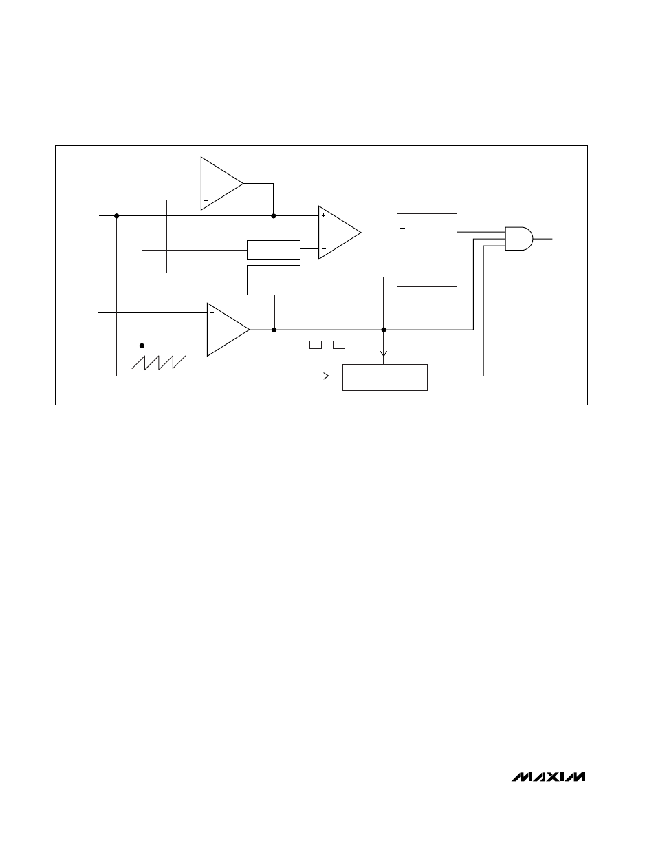
R
Q
S
CLK
REFI
DL_
FAULT
PROTECTION
ENABLE
LEVEL
SHIFT
REF
COMP
FB
DCON
OSC
SOFT-
START*
*SOFT-START RAMPS REFI FROM 0V TO V
REF
IN 1024 CLK CYCLES.
Figure 3. PWM Auxiliary Controller Block Diagram