Max1800 digital camera step-up power supply – Rainbow Electronics MAX1800 User Manual
Page 14
MAX1800
Digital Camera Step-Up
Power Supply
14
______________________________________________________________________________________
Setting the Output Voltages
Set the MAX1800 output voltages by connecting a
resistive voltage-divider from the output voltage to the
corresponding FB_ input. The FB_ input bias current is
less than 100nA, so choose R
L1
(the low-side FB_-to-
GND resistor) to be 100k
Ω. Choose R
H1
(the high-side
output-to-FB_ resistor) according to the relation:
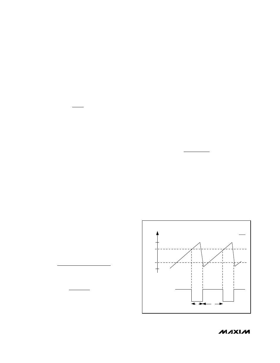
Setting the Maximum Duty Cycle
The master oscillator signal at OSC and the voltage at
DCON
_
are used to generate the internal clock signals
for the MAX1800 auxiliary controllers (CLK in Figure 3).
The internal clock’s falling edge occurs when V
OSC
exceeds V
DCON_
(set by a resistive divider). The inter-
nal clock’s rising edge occurs when V
OSC
falls below
0.25V (Figure 5).
The adjustable maximum duty-cycle range is 40% to
90% (see the Maximum Duty Cycle vs. V
DCON_
graph
in the Typical Operating Characteristics.) The maximum
duty cycle defaults to 84% at 100kHz if V
DCON_
is at or
above the voltage at V
REF
(1.25V) (see the Default
Maximum Duty Cycle vs. Frequency graph in the
Typical Operating Characteristics). The controller shuts
down if V
DCON_
is less than 0.3V.
Inductor Selection
Select the inductor for either continuous or discontinu-
ous current. Continuous conduction generally offers the
best efficiency. Use discontinuous current if the step-
up ratio (V
OUT
/ V
IN
) is greater than 1 / ( 1 - D
MAX
).
Continuous Inductor Current
A reasonable inductor value (L
IDEAL
) can be derived
from the following equation, which sets continuous
peak-to-peak inductor current at one-third the DC
inductor current:
where D, the duty cycle, is given by:
In these equations, V
SW
is the voltage drop across the
N-channel MOSFET switch, and V
D
is the forward volt-
age drop across the rectifier. Given L
IDEAL
, the consis-
tent peak-to-peak inductor current is 0.33 I
OUT
/ (1 - D).
The maximum inductor current is 1.17 I
OUT
/ (1 - D).
Inductance values smaller than L
IDEAL
can be used;
however, the maximum inductor current will rise as L is
reduced, and a larger output capacitance will be
required to maintain output ripple.
The inductor current will become discontinuous if I
OUT
decreases by more than a factor of six from the value
used to determine L
IDEAL
.
Discontinuous Inductor Current
In the discontinuous mode of operation, the MAX1800
controller regulates the output voltage by adjusting the
duty cycle to allow adequate power transfer to the load.
To ensure regulation under worst-case load conditions
(maximum I
OUT
), choose
The peak inductor current is V
IN
D
MAX
/ (L f
OSC
).
The inductor’s saturation current rating should meet or
exceed the calculated peak inductor current.
Input and Output Filter Capacitors
The input capacitor (C
IN
) in step-up designs reduces
the current peaks drawn from the battery or input
power source and reduces switching noise in the con-
troller. The impedance of the input capacitor at the
switching frequency should be less than that of the
L
V
D
I
f
OUT
MAX
OUT
OSC
=
2
D
V
V
V
IN
OUT
D
≈ −
+
1
L
V
V
D
D
I
f
IDEAL
IN MAX
SW
OUT
OSC
=
−
−
3
1
(
)
(
)
(
)
R
R
V
H
L
OUT
1
1
1 25
1
=
−
.
t
L
t
H
1.25
V
OSC
(V)
V
DCON_
0.25
0
CLK
t
H
t
L
+ t
H
D
MAX
=
Figure 5. Auxiliary Controller Internal Clock Signal Generation