Max1800 digital camera step-up power supply – Rainbow Electronics MAX1800 User Manual
Page 19
MAX1800
Digital Camera Step-Up
Power Supply
______________________________________________________________________________________
19
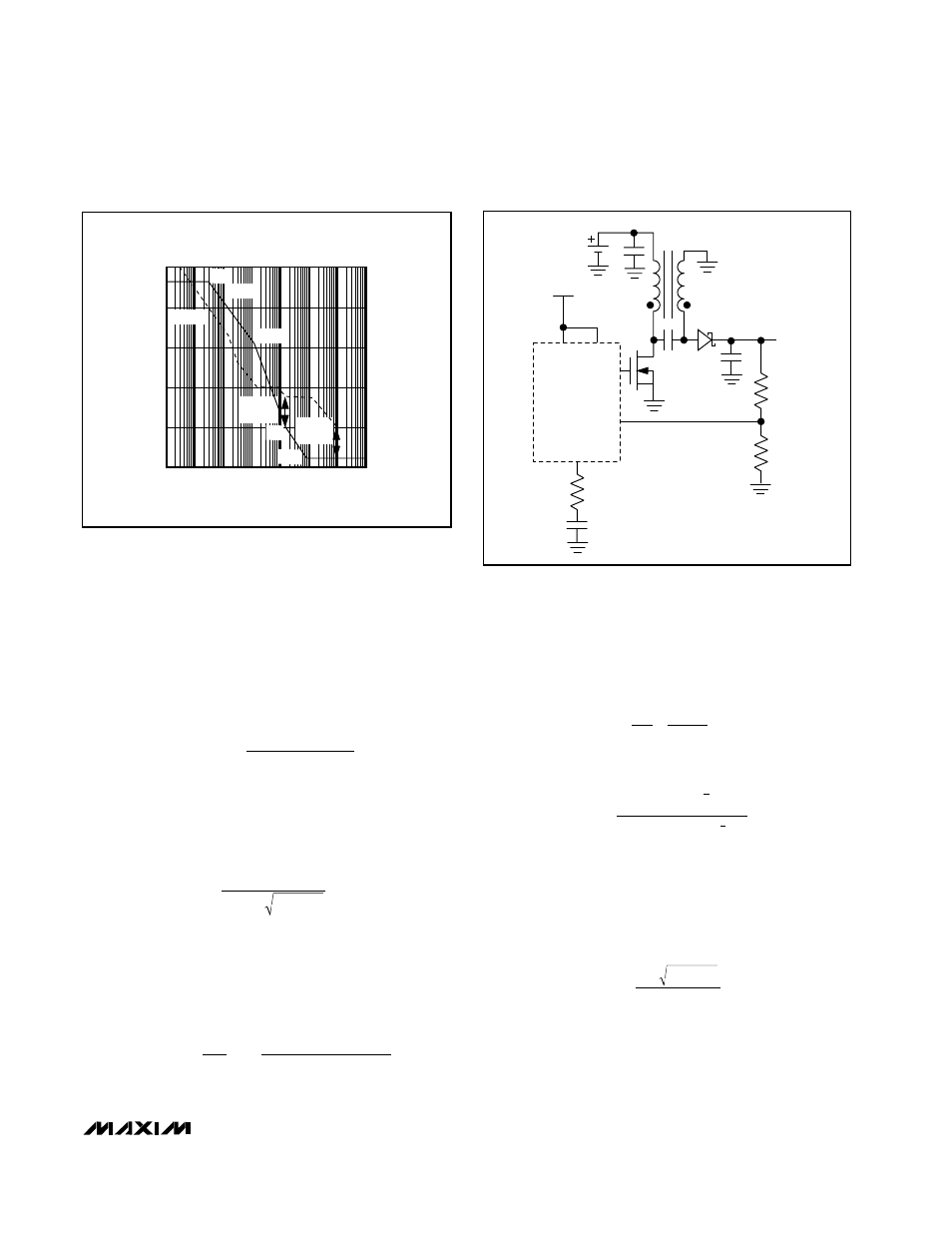
The Bode plot of the loop gain of this control circuit is
shown in Figure 7.
To configure the compensation network for a stable
control loop, set the crossover frequency at that of the
zero due to the output capacitor ESR. Use the following
procedure:
1) Determine the frequency of the right-half-plane
zero:
2) Find the DC loop gain:
A
VDC
= 2000 V
OUT
V
IN
3) Determine the frequency of the complex pole pair
due to the inductor and output capacitor:
4) Since response is 2nd order (-40dB per decade)
between the complex pole pair and the ESR zero,
determine the desired amplitude at the complex
pole pair to force the crossover frequency equal to
the ESR zero frequency. Thus:
5) Determine the desired compensation pole. Since
the response between the compensation pole and
the complex pole pair is 1st order (-20dB per
decade), the ratio of the frequencies is equal to the
ratio of the amplitudes at those frequencies. Thus:
Solving this equation for C
C
:
6) Determine that the compensation resistor, R
C
for
the compensation zero frequency, is equal to the
complex pole-pair frequency:
Z
C
= P
O
Solving for R
C
:
R
V
LC
V
C
C
IN
OUT
OUT
C
=
C
V
M
V
L
C
OUT COUT
ESR
IN
=
( )
(
)
3
2
1
2
2
20
Ω
P
P
A
A P
O
C
DC
O
=
(
)
A P
Z
P
LV
C
ESR V
O
O
O
IN
OUT
OUT
( )
=
=
2
2
2
2
f
V
V
LC
O
OUT
IN
OUT
=
2
π
Z
(1 - D) R
2 L
RHP
2
LOAD
=
π
D
1
Q
1
L
1
L
2
C
2
C
C
R
1
OUTPUT
3.3V
R
2
R
C
MAIN
IN
COMP
DCON
PART OF
MAX1800
DL
FB
INPUT
1-CELL
LITHIUM-ION
Figure 8. Auxiliary SEPIC Configuration
FREQUENCY
A
VDC
GAIN
(dB)
PHASE
180
°
90
°
0
°
O dB
PHASE
GAIN
Z
C
=P
O
PC
Z
O
Z
rRHP
PHASE
MARGIN
GAIN
MARGIN
Figure 7. MAX1800 Continuous-Current, Voltage-Mode,
Step-Up Converter Bode Plot