Electrical characteristics (continued) – Rainbow Electronics MAX3679A User Manual
Page 3
MAX3679A
+3.3V, Low-Jitter Crystal to LVPECL
Clock Generator
_______________________________________________________________________________________
3
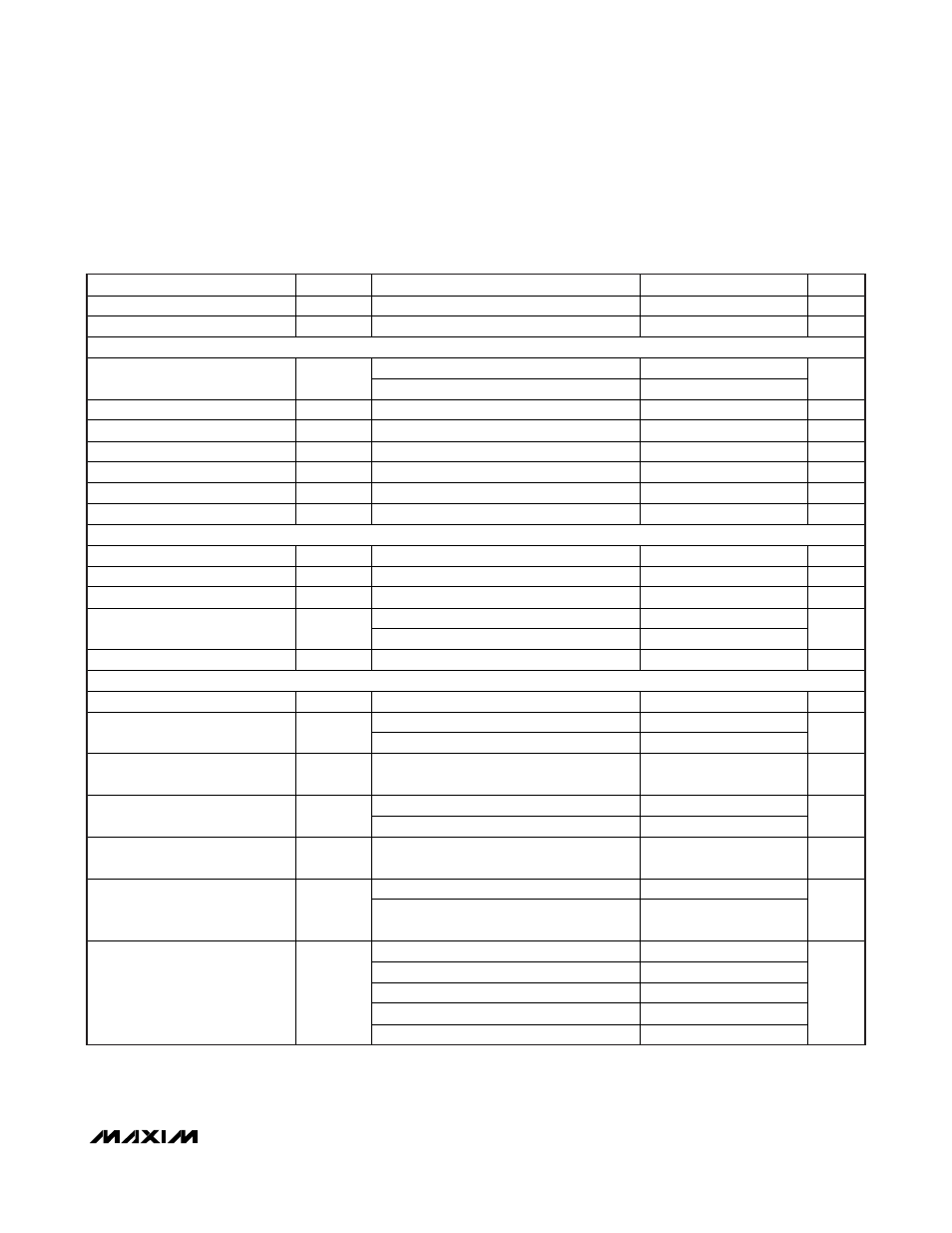
ELECTRICAL CHARACTERISTICS (continued)
(V
CC
= +3.0V to +3.6V, T
A
= -40°C to +85°C, unless otherwise noted. Typical values are at V
CC
= +3.3V, T
A
= +25°C, unless other-
wise noted.) (Notes 1, 2, and 3)
PARAMETER
SYMBOL
CONDITIONS
MIN
TYP
MAX
UNITS
Input High Current
I
IH
V
IN
= V
CC
80
μA
Input Low Current
I
IL
V
IN
= 0V
-80
μA
REF_IN SPECIFICATIONS (Input DC- or AC-Coupled)
PLL enabled
25
Reference Clock Frequency
PLL bypassed
320
MHz
Input-Voltage High
V
IH
2.0
V
Input-Voltage Low
V
IL
0.8
V
Input High Current
I
IH
V
IN
= V
CC
240
μA
Input Low Current
I
IL
V
IN
= 0V
-240
μA
Reference Clock Duty Cycle
PLL enabled
30
70
%
Input Capacitance
2.5
pF
QA_C SPECIFICATIONS
Output High Voltage
V
OH
QA_C
sourcing
12mA
2.6
V
Output Low Voltage
V
OL
QA_C sinking 12mA
0.4
V
Output Rise/Fall Time
(Notes 3, 6)
250
500
1000
ps
PLL enabled
42
50
58
Output Duty-Cycle Distortion
PLL bypassed (Note 5)
40
60
%
Output Impedance
14
CLOCK OUTPUT AC SPECIFICATIONS
VCO Frequency Range
625
MHz
12kHz to 20MHz
0.36
1.0
Random Jitter (Note 7)
RJ
RMS
1.875MHz to 20MHz
0.14
ps
RMS
Deterministic Jitter Due to
Supply Noise
LVPECL output (Notes 7, 8, 9)
5.0
ps
P-P
LVPECL output
-59
Spurs Induced by Power-Supply
Noise (Notes 7, 9, 10)
LVCMOS output
-47
dBc
Nonharmonic and Subharmonic
Spurs
-70 dBc
Between QB0 and QB1
15
Output Skew
Between QA and QB0 or QB1,
PECL outputs
20
ps
f = 1kHz
-124
f = 10kHz
-125
f = 100kHz
-130
f = 1MHz
-145
Clock Output SSB Phase Noise
at 125MHz (Note 11)
f > 10MHz
-153
dBc/Hz
Note 1:
A series resistor of up to 10.5
Ω is allowed between V
CC
and V
CCA
for filtering supply noise when system power-supply
tolerance is V
CC
= 3.3V ±5%. See Figure 2.