Register summary, Crystal selection, Data transfer summary figure 3 – Rainbow Electronics DS1202S User Manual
Page 4
DS1202, DS1202S
032697 4/11
REGISTER SUMMARY
A register data format summary is shown in Figure 4.
CRYSTAL SELECTION
A 32.768 KHz crystal, can be directly connected to the
DS1202 via pins 2 and 3 (X1, X2). The crystal selected
for use should have a specified load capacitance (CL) of
6 pF. The crystal is connected directly to the X1 and X2
pins. There is no need for external capacitors or resis-
tors. Note: X1 and X2 are very high impedance nodes.
It is recommended that they and the crystal be guard–
ringed with ground and that high frequency signals be
kept away from the crystal area. For more information
on crystal selection and crystal layout considerations,
please consult Application Note 58, “Crystal Consider-
ations with Dallas Real Time Clocks”.
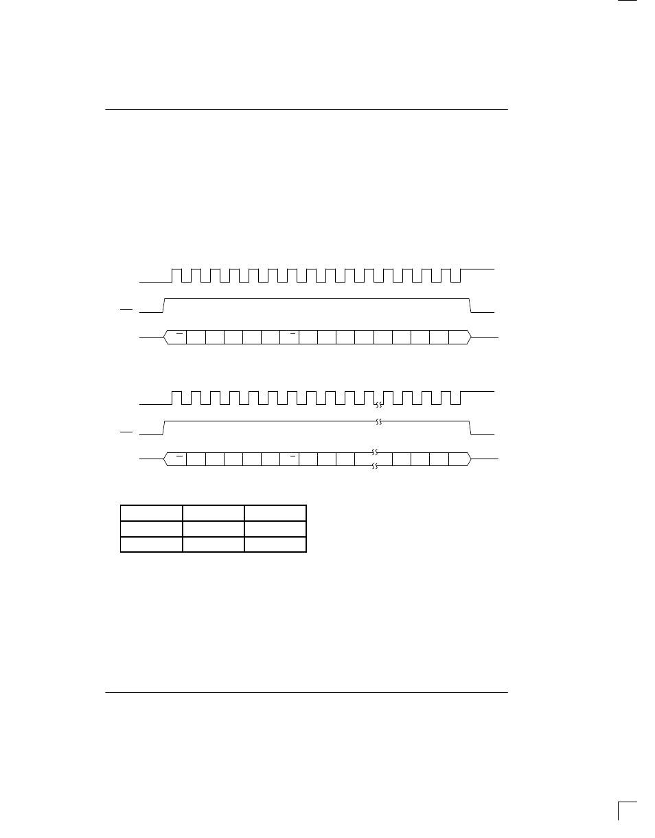
DATA TRANSFER SUMMARY Figure 3
SCLK
I/O
RST
0
1
2
3
4
5
6
7
0
1
2
3
4
5
6
7
R/W
A0
A1
A2
A3
A4
1
ADDRESS COMMAND
DATA INPUT/OUTPUT
SINGLE BYTE TRANSFER
SCLK
I/O
0
1
2
3
4
5
6
7
0
1
2
4
5
6
7
1
1
1
1
1
1
ADDRESS COMMAND
DATA I/O BYTE N
BURST MODE TRANSFER
RST
R/W
DATA I/O BYTE 1
R/C
R/C
FUNCTION
BYTE N
SCLK n
CLOCK
8
72
RAM
24
200