Ds1870 ldmos rf power-amplifier bias controller – Rainbow Electronics DS1870 User Manual
Page 24
DS1870
LDMOS RF Power-Amplifier Bias
Controller
24
____________________________________________________________________
I2C Definitions
The following terminology is commonly used to
describe I
2
C data transfers.
Master device: The master device controls the slave
devices on the bus. The master device generates SCL
clock pulses, and start and stop conditions.
Slave devices: Slave devices send and receive data at
the master’s request.
Bus idle or not busy: Time between stop and start
conditions when both SDA and SCL are inactive and in
their logic high states. When the bus is idle, it often initi-
ates a low-power mode for slave devices.
Start condition: A start condition is generated by the
master to initiate a new data transfer with a slave.
Transitioning SDA from high to low while SCL remains
high generates a start condition. See the timing dia-
gram for applicable timing.
Stop condition: A stop condition is generated by the
master to end a data transfer with a slave. Transitioning
SDA from low to high while SCL remains high gener-
ates a stop condition. See the timing diagram for
applicable timing.
Repeated start condition: The master can use a
repeated start condition at the end of one data transfer
to indicate that it will immediately initiate a new data
transfer following the current one. Repeated starts are
commonly used during read operations to identify a
specific memory address to begin a data transfer. A
repeated start condition is issued identically to a nor-
mal start condition. See the timing diagram for applica-
ble timing.
Bit write: Transitions of SDA must occur during the low
state of SCL. The data on SDA must remain valid and
unchanged during the entire high pulse of SCL plus the
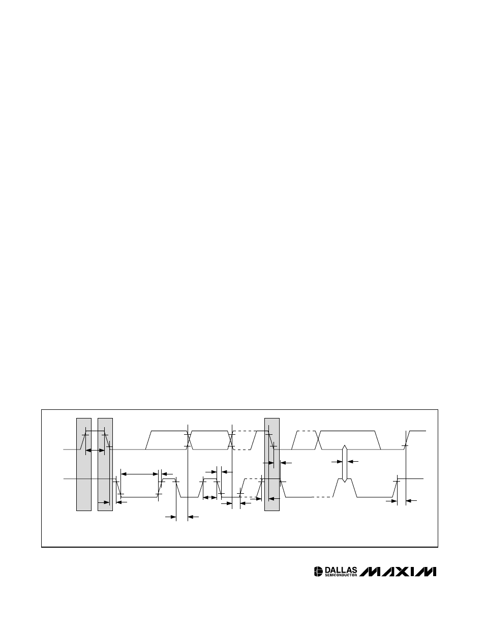
SDA
SCL
t
HD:STA
t
LOW
t
HIGH
t
R
t
F
t
BUF
t
HD:DAT
t
SU:DAT
REPEATED
START
t
SU:STA
t
HD:STA
t
SU:STO
t
SP
STOP
NOTE: TIMING IS REFERENCED TO V
IL(MAX)
AND V
IH(MIN)
.
START
Figure 3. I
2
C Timing Diagram
TABLE 2 (TEMP LUT FOR POT 1)
Bytes 80h–C7h
POT1
TABLE 3 (TEMP LUT FOR POT 2)
Bytes 80h–C7h
POT2
TABLE 4 (DRAIN LUT FOR POT 1)
Bytes 80h–B8h
POT1 Off
TABLE 5 (DRAIN LUT FOR POT 2)
Bytes 80h–B8h
POT2 Off