Data retention mode, Oscillator control, Microprocessor monitor – Rainbow Electronics DS1672 User Manual
Page 8: Trickle charger
DS1672
8 of 12
Data Retention Mode
The device is fully accessible and data can be written and ready only when V
CC
is greater than V
PF
.
However, when V
CC
falls below V
PF
, (point at which write protection occurs) the internal clock registers
are blocked from any access. If V
PF
is less than V
BACKUP
, the device power is switched from V
CC
to
V
BACKUP
when V
CC
drops below V
PF
. If V
PF
is greater than V
BACKUP
, the device power is switched from
V
CC
to V
BACKUP
when V
CC
drops below V
BACKUP
. The registers are maintained from the V
BACKUP
source
until V
CC
is returned to nominal levels.
Oscillator Control
The
EOSC
bit (bit 7 of the control register) controls the oscillator when in back-up mode. This bit when
set to logic 0 will start the oscillator. When this bit is set to a logic 1, the oscillator is stopped and the
DS1672 is placed into a low-power standby mode (I
BACKUP
) when in back-up mode. When the DS1672 is
powered by V
CC,
the oscillator is always on regardless of the status of the
EOSC
bit; however, the counter
is incremented only when
EOSC
is a logic 0.
Microprocessor Monitor
A temperature-compensated comparator circuit monitors the level of V
CC
. When V
CC
falls to the power-
fail trip point, the
RST
signal (open drain) is pulled active. When V
CC
returns to nominal levels, the
RST
signal is kept in the active state for 250ms (typically) to allow the power supply and microprocessor to
stabilize. Note, however, that if the
EOSC
bit is set to a logic 1 (to disable the oscillator during write
protection), the reset signal will be kept in an active state for 250ms plus the startup time of the oscillator.
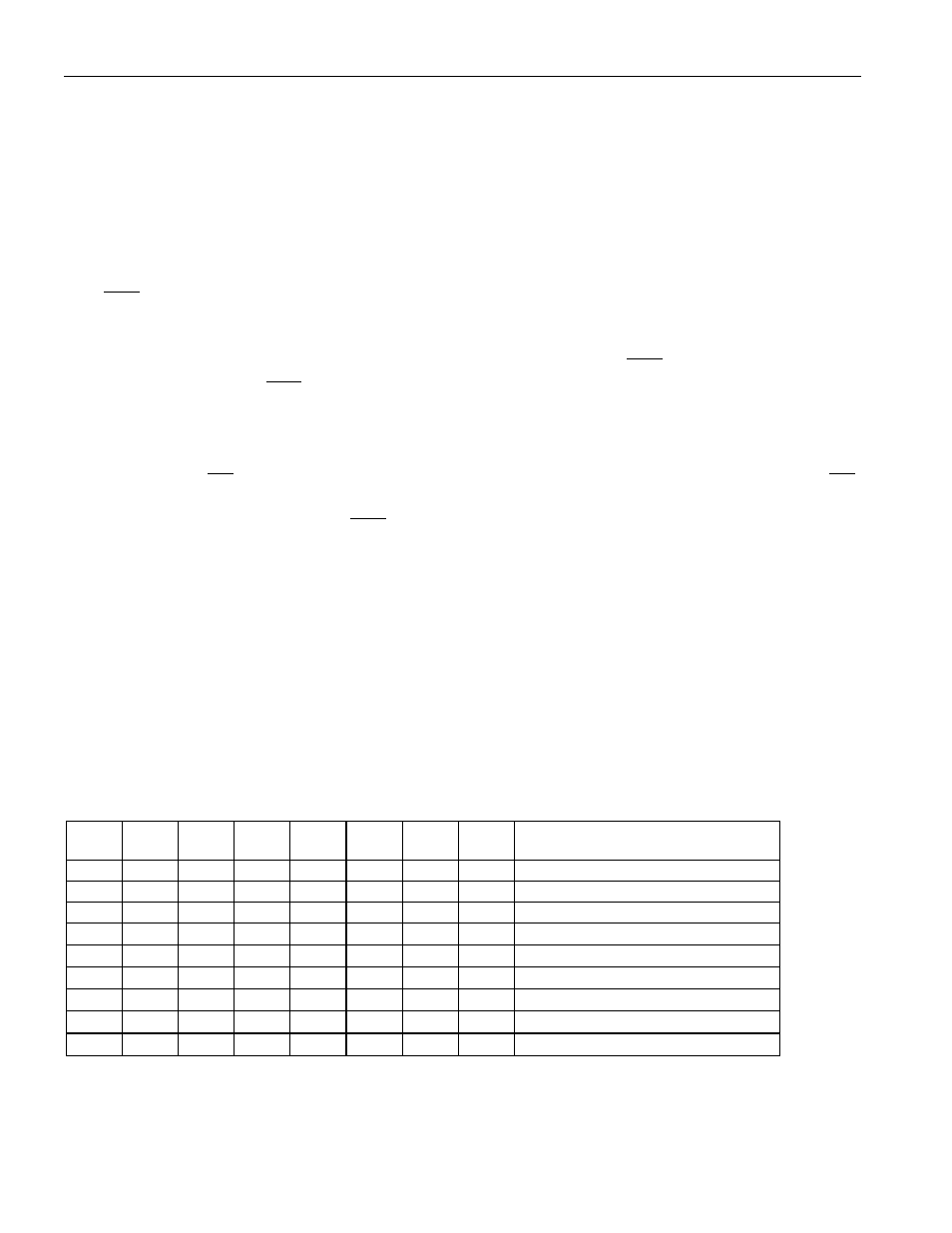
Trickle Charger
The trickle charger is controlled by the trickle charge register. The simplified schematic of Figure 5
shows the basic components of the trickle charger. The trickle charge select (TCS) bit (bits 4–7) controls
the selection of the trickle charger. In order to prevent accidental enabling, only a pattern on 1010 will
enable the trickle charger. All other patterns will disable the trickle charger. The DS1672 powers up with
the trickle charger disabled. The diode select (DS) bits (bits 2, 3) select whether or not a diode is
connected between V
CC
and V
BACKUP
. If DS is 01, no diode is selected or if DS is 10, a diode is selected.
The RS bits (bits 0, 1) select whether a resistor is connected between V
CC
and V
BACKUP
and
what the value
of the resistor is. The resistor selected by the resistor select (RS) bits and the diode selected by the diode
select (DS) bits are as follows:
TCS
TCS
TCS
TCS
DS
DS
RS
RS
FUNCTION
X
X
X
X
0
0
X
X
Disabled
X
X
X
X
1
1
X
X
Disabled
X
X
X
X
X
X
0
0
Disabled
1
0
1
0
0
1
0
1
No diode, 250
W resistor
1
0
1
0
1
0
0
1
One diode, 250
W resistor
1
0
1
0
0
1
1
0
No diode, 2k
W resistor
1
0
1
0
1
0
1
0
One diode, 2k
W resistor
1
0
1
0
0
1
1
1
No diode, 4k
W resistor
1
0
1
0
1
0
1
1
One diode, 4k
W resistor