Power-up/power-down characteristics, Figure 1. timing diagram, Figure 2. power-up/power-down timing – Rainbow Electronics DS1672 User Manual
Page 5: 40 °c to +85°c), Detect to, Falling) t, 10 µs v, Rising) t, Fall time; v, 300 ms v
DS1672
5 of 12
POWER-UP/POWER-DOWN CHARACTERISTICS
(T
A
= -40
°C to +85°C)
PARAMETER
SYMBOL
MIN
TYP
MAX
UNITS
NOTES
V
CC
Detect to
RST
(V
CC
Falling)
t
RPD
10
µs
V
CC
Detect to
RST
(V
CC
Rising)
t
RPU
250
ms
11
V
CC
Fall Time; V
PF(MAX)
to V
PF(MIN)
t
F
300
ms
V
CC
Rise Time; V
PF(MIN)
to V
PF(MAX)
t
R
0
ms
Note 11: If the
EOSC
bit in the control register is set to logic 1, t
RPU
is equal to 250ms plus the startup time of the crystal oscillator.
Warning: Under no circumstances are negative undershoots, of any amplitude, allowed when device is in write
protection.
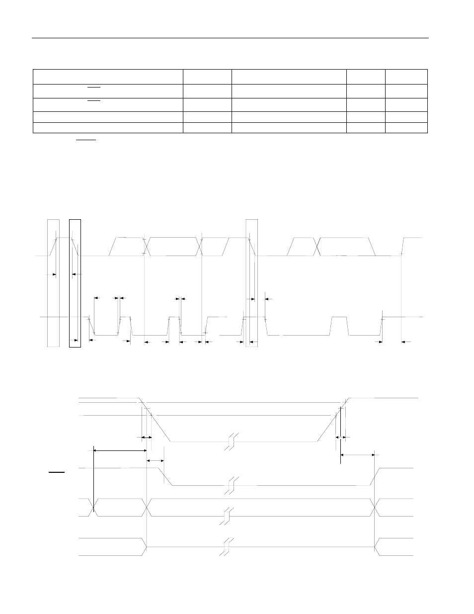
Figure 1. Timing Diagram
SCL
START
SDA
STOP
t
BUF
REPEATED
START
t
HD:STA
t
LOW
t
HD:STA
t
HD:DAT
t
SU:DAT
t
HIGH
t
SU:STA
t
F
t
SU:STO
Figure 2. Power-Up/Power-Down Timing
OUTPUTS
V
CC
V
PF(max)
INPUTS
HIGH-Z
RST
DON'T CARE
VALID
RECOGNIZED
RECOGNIZED
VALID
t
RPD
V
PF(min)
t
F
t
PD
t
R
t
RPU
- MAX6869 (17 pages)
- TNY-A9260-C01 (5 pages)
- MAX34441 (53 pages)
- MAX4912 (13 pages)
- QIL-A9260-C11 (20 pages)
- QIL-A9260-C11 (1 page)
- QIL-A9260-C11 (34 pages)
- USB-A9263-C02 (1 page)
- DAB-GPS-C01 (15 pages)
- DAB-GPS-C01 (28 pages)
- DAB-CAM-C01 (27 pages)
- DAB-WLS-C01 (WiFi) (20 pages)
- USB-A9G20-C01 (1 page)
- MAX34440 (43 pages)
- SBC35-A9260-C12 (28 pages)
- SBC35-A9260-C12 (1 page)
- MAX16024 (17 pages)
- USB-A9G20-C11 (5 pages)
- DAB-IMU-C01 (20 pages)
- MAX16021 (21 pages)
- DAB-WLS-C11 (BlueTooth) (2 pages)
- SBC35-A9G20-C11 (24 pages)
- MAX16054 (9 pages)
- MAX14525 (7 pages)
- MAX16066 (61 pages)
- USB-A9260-C12 (1 page)
- DS1803 (11 pages)
- DS12887A (2 pages)
- DS1339 (18 pages)
- DS1858 (22 pages)
- DS1267 (12 pages)
- DS12С887A (2 pages)
- DS1804 (7 pages)
- DS1091L (6 pages)
- DS1669S (10 pages)
- DS1867 (14 pages)
- DS1087L (12 pages)
- DS4026 (13 pages)
- DS1286 (13 pages)
- DS1801 (10 pages)
- DS1254 (17 pages)
- DS17887 (38 pages)
- DS1691 (4 pages)
- DS1615 (24 pages)
- DS1868 (14 pages)