Motor driver ics ba6950fs – Rainbow Electronics BA6950FS User Manual
Page 5
488
Motor driver ICs
BA6950FS
F
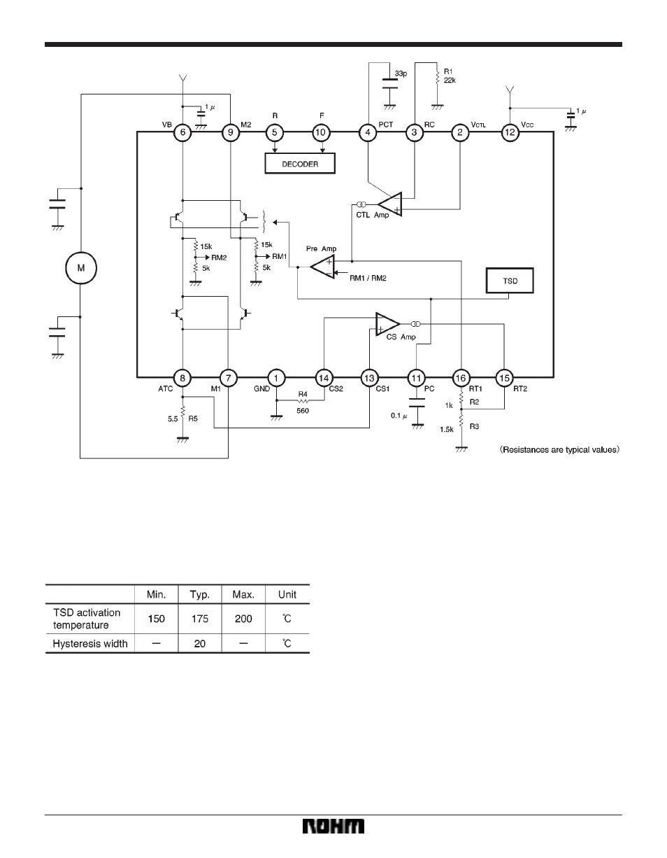
Application example
F
Operation notes
(1)
Thermal shutdown circuit
The thermal shutdown (TSD) circuit turns off all driver
outputs when the IC junction temperature rises above
175
_
C (Typ.). The temperature difference between the
activation and deactivation settings is about 20
_
C.
S
Temperature setting of TSD
(2)
Control logic and control signal input pins
Voltage should never be applied to the control logic input
pins (pins 5 and 10) or the control signal input pin (pin 2)
when the V
CC
voltage is not applied to the IC. Similarly,
the voltage on each input pin should not exceed any ap-
plied V
CC
voltage.
(3)
PCB arrangement
When changing the rotational direction of a motor, a large
current of up to a few hundred milliamperes can flow be-
tween the motor power supply (pin 6) and RNF (pin 8).
Depending on the application, this large output current
may flow back to input pins, resulting in output oscillation
or other malfunctions. Make sure that your design does
not allow a common impedance between the large cur-
rent output lines and the input section. Suppress the
power supply impedance to low levels, otherwise output
oscillation may occur.
(4)
Package power
The power dissipated by the IC varies widely with the
supply voltage and the output current. Give full consider-
ation to the package power dissipation rating when set-
ting the supply voltage and the output current.
(5)
The input pins (pins 5 and 10) have temperature-
dependent characteristics. Take the temperature effect
into consideration when using the IC.
(6)
To eliminate motor noise, connect a capacitor be-
tween M1 (pin 7) and GND and between M2 (pin 9) and
GND.
Fig.4