Motor driver ics ba6950fs – Rainbow Electronics BA6950FS User Manual
Page 4
487
Motor driver ICs
BA6950FS
F
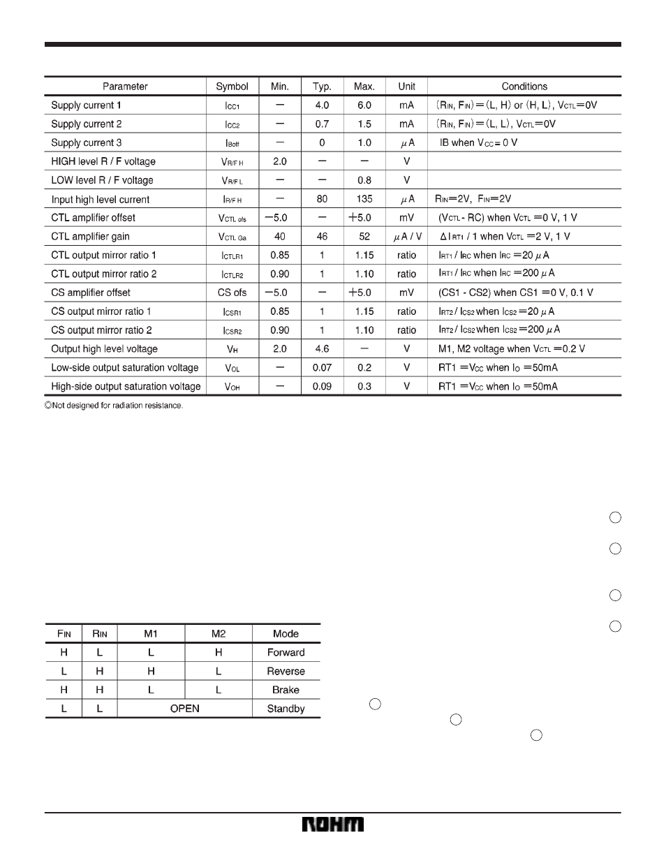
Electrical characteristics (unless otherwise noted, Ta = 25
_
C, V
CC
= 4.8V, VB = 4.8V)
F
Circuit operation
(1)
Input section (F
IN
, R
IN
)
Control signals are input from these pins. Current flows
from M2 to M1 (forward mode) when F
IN
is HIGH and R
IN
is LOW, and from M1 to M2 (reverse mode) when R
IN
is
HIGH and F
IN
is LOW. Putting F
IN
and R
IN
both HIGH re-
sults in the brake mode in which the high-side output
transistor is turned off to shut down the motor driving cur-
rent and the low-side output transistor is turned ON to ab-
sorb the counter-electromotive force of the motor, so that
a brake is put on the motor. When F
IN
and R
IN
are both
LOW, both M1 and M2 are left open and the motor stops.
Input / output truth table
(2)
Output section (M1, M2)
Two logic inputs control the motor by changing the status
of bridge-configured transistors.
(3)
Output high level voltage
Values of current, voltage, and HIGH level output voltage
can be set as follows by using external resistors (refer to
the application circuit of Fig. 4).
S
I16 pin (I
RT1
)
I16 pin (I
RT1
) = V2 pin/R1
S
S
S
1
S
I15 pin (I
RT2
)
I15 pin (I
RT2
) = I8 pin
R5/R4
S
S
S
2
S
V16 pin (V
RT1
)
V16 pin = R3
(I16 pin
)
I15 pin)
)
R2
I16 pin
S
S
S
3
S
V7, 9 pin (M1, M2 voltage; high-side voltage)
V7, 9 pin = 4
V16 pin (Typ.)
S
S
S
4
(4)
Current feedback amplifier
The pin-8 current is increased when the motor rotational
speed is reduced by loading, and the current feedback
amplifier increases the pin-15 current according to equa-
tion
2
. Because the pin-16 voltage then increases ac-
cording to equation
3
, the HIGH level output voltage
also increases according to equation
4
. In this way, the
rotational speed is kept constant by increasing the volt-
age applied to the motor.