Warning, Capacitance – Rainbow Electronics DS1393 User Manual
Page 8
DS1390/DS1391/DS1392/DS1393
Low-Voltage SPI/3-Wire RTCs with
Trickle Charger
8
_____________________________________________________________________
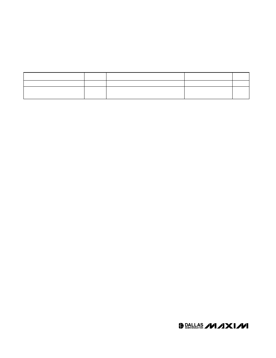
CAPACITANCE
(T
A
= +25°C)
PARAMETER
SYMBOL
CONDITIONS
MIN
TYP
MAX
UNITS
Capacitance on All Input Pins
C
IN
10
pF
Capacitance on All Output Pins
(High Impedance)
C
IO
10
pF
WARNING:
Under no circumstances are negative undershoots, of any amplitude, allowed when the device
is in write protection.
Note 1:
Limits at -40°C are guaranteed by design and not production tested.
Note 2:
All voltages are referenced to ground.
Note 3:
The use of the 250
Ω trickle-charge resistor is not allowed at V
CC
> 3.63V and should not be enabled. Use of the diode is
not recommended for V
CC
< 3.0V.
Note 4:
Measured at V
CC
= typ, V
BACKUP
= 0V, register 0Fh = A5h.
Note 5:
Measured at V
CC
= typ, V
BACKUP
= 0V, register 0Fh = A6h.
Note 6:
Measured at V
CC
= typ, V
BACKUP
= 0V, register 0Fh = A7h.
Note 7:
SCLK, DIN, CS on DS1390/DS1391; SCLK, and CE on DS1392/DS1393.
Note 8:
DOUT, SQW/INT (DS1390/DS1393), SQW, and INT (DS1392).
Note 9:
The RST pin has an internal 50k
Ω (typ) pullup resistor to V
CC
.
Note 10: I
CCA
—SCLK clocking at max frequency = 4MHz for 3V and 3.3V versions; 1MHz for 1.8V version; RST (DS1391/DS1393)
inactive. Outputs are open.
Note 11: Specified with bus inactive.
Note 12: Measured with a 32.768kHz crystal attached to X1 and X2. Typical values measured at +25°C and 3.0V
BACKUP
.
Note 13: With 50pF load.
Note 14: Measured at V
IH
= 0.7 x V
DD
or V
IL
= 0.2 x V
DD
, 10ns rise/fall times.
Note 15: Measured at V
OH
= 0.7 x V
DD
or V
OL
= 0.2 x V
DD
. Measured from the 50% point of SCLK to the V
OH
minimum of SDO.
Note 16: The parameter t
OSF
is the time that the oscillator must be stopped for the OSF flag to be set over the voltage range of
0
≤ V
CC
≤ V
CC(MAX)
and 1.3V
≤ V
BAT
≤ 5.5V.
Note 17: This delay applies only if the oscillator is enabled and running. If the EOSC bit is 1, the startup time of the oscillator is
added to this delay.