Atmega32(l) – Rainbow Electronics ATmega32L User Manual
Page 35
35
ATmega32(L)
2503C–AVR–10/02
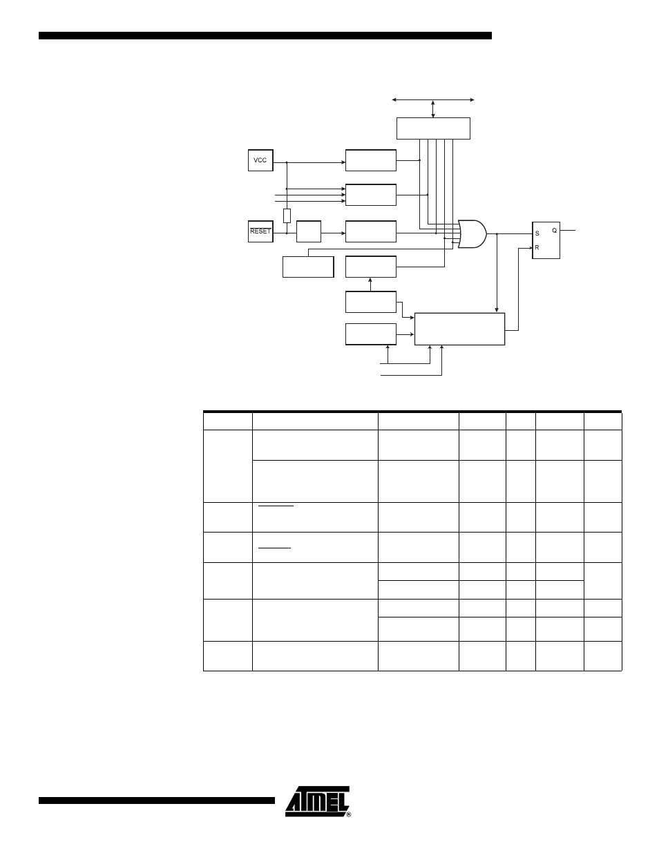
Figure 15. Reset Logic
Notes:
1. The Power-on Reset will not work unless the supply voltage has been below V
POT
(falling).
2. V
BOT
may be below nominal minimum operating voltage for some devices. For
devices where this is the case, the device is tested down to V
CC
= V
BOT
during the
production test. This guarantees that a Brown-out Reset will occur before V
CC
drops
to a voltage where correct operation of the microcontroller is no longer guaranteed.
The test is performed using BODLEVEL = 1 for ATmega32L and BODLEVEL = 0 for
ATmega32. BODLEVEL = 1 is not applicable for ATmega32.
Table 15. Reset Characteristics
Symbol
Parameter
Condition
Min
Typ
Max
Units
V
POT
Power-on Reset
Threshold Voltage (rising)
1.4
2.3
V
Power-on Reset
Threshold Voltage
(falling)
(1)
1.3
2.3
V
V
RST
RESET Pin Threshold
Voltage
0.2 V
CC
0.85V
CC
V
t
RST
Minimum pulse width on
RESET Pin
50
ns
V
BOT
Brown-out Reset
Threshold Voltage
(2)
BODLEVEL = 1
2.5
2.7
3.2
V
BODLEVEL = 0
3.7
4.0
4.2
t
BOD
Minimum low voltage
period for Brown-out
Detection
BODLEVEL = 1
2
µs
BODLEVEL = 0
2
µs
V
HYST
Brown-out Detector
hysteresis
50
mV
MCU Control and Status
Register (MCUCSR)
BODEN
BODLEVEL
Delay Counters
CKSEL[3:0]
CK
TIMEOUT
WDRF
BORF
EXTRF
PORF
DATA BUS
Clock
Generator
SPIKE
FILTER
Pull-up Resistor
JTRF
JTAG Reset
Register
Watchdog
Oscillator
SUT[1:0]
Watchdog
Timer
Reset Circuit
Brown-out
Reset Circuit
Power-on
Reset Circuit
INTERNAL RESET
COUNTER RESET