Ds3501 high-voltage, nv, i, C pot with temp sensor and lookup table – Rainbow Electronics DS3501 User Manual
Page 9
DS3501
High-Voltage, NV, I
2
C POT with Temp Sensor
and Lookup Table
_____________________________________________________________________
9
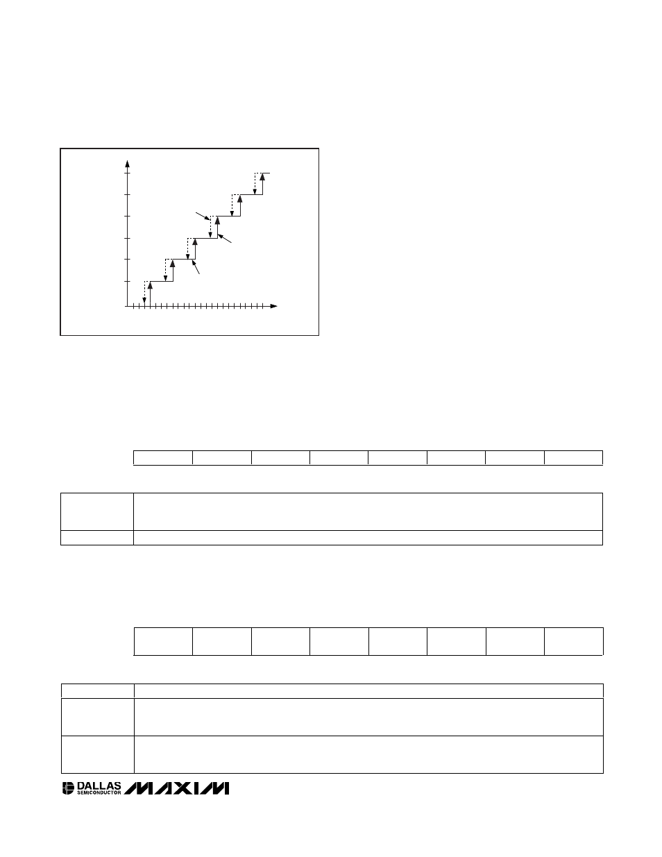
falls on the boundary between two windows. As the
temperature increases, the LUT changes on even tem-
perature values (see Figure 1). Conversely, the LUT
changes on odd temperature values when the tempera-
ture is decreasing.
LUT Adder Mode
LUT Adder Mode is selected by setting the Update
Mode bit (CR1.0) to 1 and the Adder Mode bit (CR1.1)
to 1. This mode operates similar to LUT Mode with one
major difference (see the LUT Mode and LUT Adder
Mode Block Diagram). The Wiper Register is loaded
with the sum of LUTVAL and IVR. Furthermore, in this
mode, the values programmed into the LUT are signed
two’s complement. This allows convenient positive or
negative offsetting of the nominal IVR value.
MEMOR
Y LOCA
TION
LUT20
LUT19
LUT18
LUT17
LUT16
24
28
32
36
40
44
INCREASING
TEMPERATURE
TEMPERATURE (
°C)
1
°C HYSTERESIS
WINDOW
DECREASING
TEMPERATURE
Figure 1. LUT Hysteresis
Control Register 1 (CR1)
FACTORY DEFAULT
00h
MEMORY TYPE
Shadowed Nonvolatile
03h
Reserved
Reserved
Reserved
Reserved
Reserved
Reserved
Adder
Mode
Update
Mode
bit7
bit0
bit7:2
Reserved
bit1
Adder Mode: This bit is valid only if the Update Mode bit = 1.
0 = Sets the DS3501 to LUT Mode.
1 = Sets the DS3501 to LUT Adder Mode.
bit0
Update Mode:
0 = Sets the DS3501 to Default Mode. In this mode the DS3501 is compatible with the ISL95311 (default).
1 = Sets the DS3501 to one of the two LUT-based modes depending on the Adder Mode bit.
Control Register 0 (CR0)
POWER-UP DEFAULT
00h
MEMORY TYPE
Volatile
02h
SEE
Reserved
Reserved
Reserved
Reserved
Reserved
Reserved
Reserved
bit7
bit0
bit7
SEE: Controls functionality of shadowed NV registers (such as the WR/IVR register).
0 = Data written to shadowed NV memory is stored in both SRAM and EEPROM (default).
1 = Data written to shadowed NV memory is stored only in SRAM.
bit6:0
Reserved
DS3501 Control Registers
The DS3501 contains three control registers (CR0, CR1, and CR2) used to configure and control modes and features.