Figure 7, D in – Rainbow Electronics DS89C450 User Manual
Page 28
DS89C430/DS89C440/DS89C450 Ultra-High-Speed Flash Microcontrollers
28 of 48
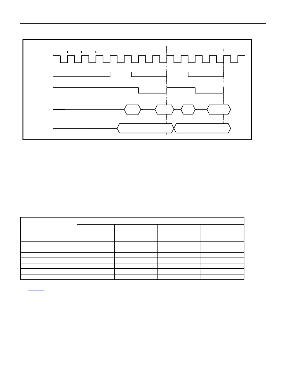
Figure 7. External Program Memory Access (Nonpage Mode, CD1:CD0 = 10)
Internal Memory Cycles
C2
C3 C4 C1 C2 C3 C4
XTAL1
ALE
Port 0
Port 2
PSEN
C1
External Memory Cycle
External Memory Cycle
MSB Add MSB Add
LSB Add Data LSB Add Data
External Data Memory Interface in Nonpage Mode Operation
Just like the program memory cycle, the external data memory cycle is four times slower than the internal data
memory cycle in nonpage mode. A basic internal memory cycle contains one system clock and a basic external
memory cycle contains four system clocks for nonpage mode operation.
The DS89C430 allows software to adjust the speed of external data memory access by stretching the memory bus
cycle. CKCON (8Eh) provides an application-selectable stretch value for this purpose. Software can change the
stretch value dynamically by changing the setting of CKCON.2–CKCON.0.
shows the data memory cycle
stretch values and their effect on the external MOVX memory bus cycle and the control signal pulse width in terms
of the number of oscillator clocks. A stretch machine cycle always contains four system clocks.
Table 6. Data Memory Cycle Stretch Values
RD/WR PULSE WIDTH (IN NUMBER OF OSCILLATOR CLOCKS)
MD2:MD0
STRETCH
CYCLES
4X/
2X, CD1,
CD0 = 100
4X/
2X, CD1,
CD0 = 000
4X/
2X, CD1,
CD0 = X10
4X/
2X, CD1,
CD0 = X11
000 0 0.5
1
2
2048
001 1
1
2
4
4096
010 2
2
4
8
8192
011 3
3
6
12
12,288
100 7
4
8
16
16,384
101 8
5
10
20
20,480
110 9
6
12
24
24,576
111 10
7
14
28
28,672
As
shows, the stretch feature supports eight stretched external data memory access cycles, which can be
categorized into three timing groups. When the stretch value is cleared to 000b, there is no stretch on external data
memory access and a MOVX instruction is completed in two basic memory cycles. When the stretch value is set to
1, 2, or 3, the external data memory access is extended by 1, 2, or 3 stretch machine cycles, respectively. Note
that the first stretch value does not result in adding four system clocks to the
RD/WR control signals. This is
because the first stretch uses one system clock to create additional setup time and one system clock to create
additional address hold time. When using very slow RAM and peripherals, a larger stretch value (4–7) can be
selected. In this stretch category, one stretch machine cycle (4 system clocks) is used to stretch the ALE pulse
width, one stretch machine cycle is used to create additional setup, one stretch machine cycle is used to create
additional hold time, and one stretch machine cycle is added to the
RD or WR strobes.