Package drawing, 3ts1 - shrink sot – Rainbow Electronics AT88SA100S User Manual
Page 19
AT88SA100S [ Preliminary]
19
8558A–SMEM–03/09
6.
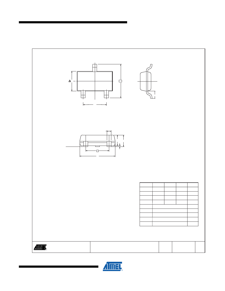
Package Drawing
3TS1 - Shrink SOT
Package Drawing Contact:
[email protected]
TITLE
DRAWING NO.
GPC
R
REV.
3TS1
11/5/08
COMMON DIMENSIONS
(Unit of Measure = mm)
SYMBOL
MIN
NOM
MAX
NOTE
End View
Side View
Top View
3TS1, 3-lead, 1.30 mm Body, PlasticThin
Shrink Small OutlinePackage (Shrink SOT)
A
TBG
0.89
0.01
0.88
2.80
2.10
1.20
0.30
A
A1
A2
D
E
E1
L1
e1
b
-
-
-
2.90
-
1.30
0.54 REF
1.90 BSC
-
1.12
0.10
1.02
3.04
2.64
1.40
0.50
1,2
1,2
3
Notes:
1.
Dimension D does not include mold flash, protrusions or gate burrs.
Mold flash, protrusions or gate burrs shall not exceed 0.25 mm per
end. Dimension E1 does not include interlead flash or protrusion.
Interlead flash or protrusion shall not exceed 0.25 mm per side.
2. The package top may be smaller than the package bottom. Dimen-
sions D and E1 are determined at the outermost extremes of the
plastic body exclusive of mold flash, tie bar burrs, gate burrs and
interlead flash, but including any mismatch between the top and
bottom of the plastic body.
3. These dimensions apply to the flat section of the lead between 0.08
mm and 0.15 mm from the lead tip.
This drawing is for general information only. Refer to JEDEC Drawing
TO-236, Variation AB for additional information.
C
L
L1
3
E
E1
1
2
e1
SEATING
PLANE
b
A2
A
A1
e
D