Ata6831, Application circuit, Figure 10-1. application circuit – Rainbow Electronics ATA6831 User Manual
Page 14: Connect the blocking capacitors at v, And v, Recommended value for capacitors at v, Micro- controller m m
14
4908D–AUTO–09/06
ATA6831
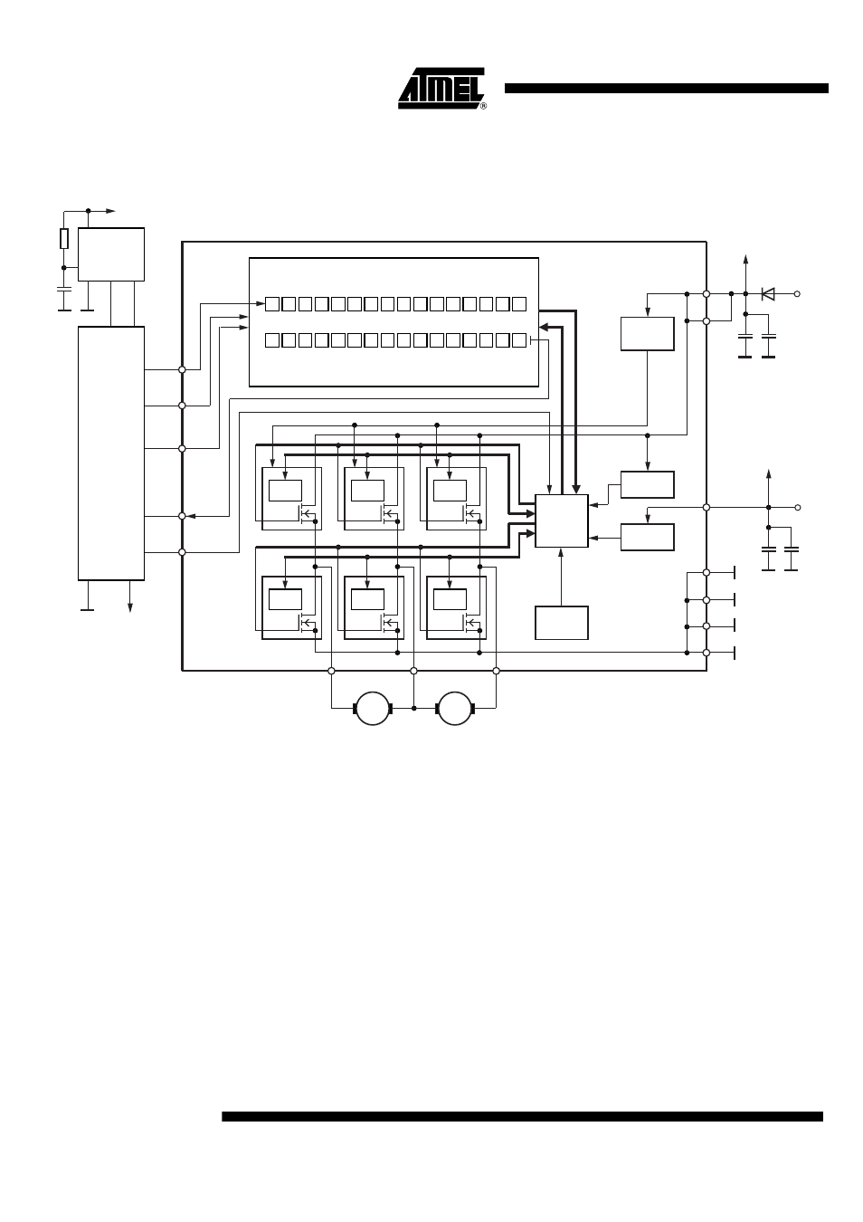
10. Application Circuit
Figure 10-1. Application Circuit
10.1
Application Notes
• Connect the blocking capacitors at V
CC
and V
S
as close as possible to the power supply and
GND pins.
• Recommended value for capacitors at V
S
:
– Electrolytic capacitor C > 22 µF in parallel with a ceramic capacitor C = 100 nF. The
value for the electrolytic capacitor depends on external loads, conducted
interferences, and the reverse conducting current I
Out1,2,3
.
• Recommended value for capacitors at V
CC
:
– Electrolytic capacitor C > 10 µF in parallel with a ceramic capacitor C = 100 nF.
• To reduce thermal resistance, place cooling areas on the PCB as close as possible to the
GND pins and to the die pad.
Fault
detector
Fault
detector
S
I
H
S
2
L
S
2
H
S
1
L
S
1
Control
logic
5
CLK
6
PWM
7
DO
3
CS
4
DI
Input register
Ouput register
Serial interface
H
S
3
L
S
3
H
S
2
L
S
2
H
S
1
L
S
1
S
R
R
H
S
3
L
S
3
O
L
D
P
H
2
P
L
2
P
H
1
P
L
1
P
H
3
P
L
3
P
S
F
Fault
detector
n.
u.
n.
u.
n.
u.
T
P
n.
u.
n.
u.
n.
u.
I
N
H
O
V
L
Fault
detector
Fault
detector
Power on
reset
Charge
pump
UV
protection
Thermal
protection
Fault
detector
VS1
10
VS2
11
VCC
9
GND
18
GND
17
GND
14
GND
8
OUT3
2
OUT1
15
OUT2
12
O
S
C
V
CC
V
CC
U5021M
Watchdog
Reset
T
rigger
Micro-
controller
M
M
V
CC
+
V
S
13V
V
Batt
5V
V
CC
BYV28
+