Rainbow Electronics DS2417 User Manual
Page 4
DS2417
4 of 15
TIMEKEEPING
A 32.768kHz crystal oscillator is used as the time base for the real-time clock counter. The oscillator can
be turned on or off under software control. The oscillator must be on for the real-time clock to function.
The real-time clock counter is double buffered. This allows the master to read time without the data
changing while it is being read. To accomplish this, a snapshot of the counter data is transferred to a
read/write buffer, which the user accesses.
DEVICE CONTROL BYTE
The DS2417 can generate interrupt pulses to trigger activities that have to occur at regular intervals. The
selection of this interval and the on/off control of the 32.768kHz crystal oscillator are done through the
device control byte. This byte can be read and written through the Clock Function commands.
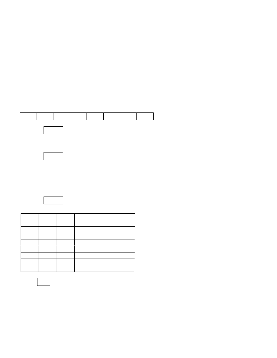
Device Control Byte
7
6
5
4
3
2
1
0
IE
IS2
IS1
IS0
OSC OSC
0
0
Bit 0 - 1
0
No function
Bits 0 and 1 are hard-wired to read all 0’s.
Bit 2 - 3
OSC Oscillator Enable/Disable
These bits control/report whether the 32.768kHz crystal oscillator is running. If the oscillator is running,
both OSC bits will read 1. If the oscillator is turned off these bits will all read 0. When writing the
device control byte both occurrences of the OSC bit should have identical data. Otherwise, the value in
bit address 3 (bold) takes precedence.
Bit 4 - 6
IS
Interval Select
These bits determine the time between interrupt pulses. The values available are shown below.
IS2
IS1
IS0
Interrupt Interval
0
0
0
1s
0
0
1
4s
0
1
0
32s
= 0.53 min.
0
1
1
64s
= 1.07 min.
1
0
0
2048s
= 34.13 min.
1
0
1
4096s
= 68.27 min.
1
1
0
65536s = 18.20 hours
1
1
1
131072s = 36.41 hours
Bit 7
IE Interrupt Enable
This bit controls whether the interrupt pulse will be generated at the selected interval. To enable
interrupts this bit needs to be 1.