Detailed pin description, Block diagram figure 1, Bit lasered rom – Rainbow Electronics DS2417 User Manual
Page 2
DS2417
2 of 15
is successfully executed, the real-time clock functions become accessible and the master may then
provide one of the real-time clock function commands. The protocol for these commands is described in
Figure 5. All data is read and written least significant bit first.
DETAILED PIN DESCRIPTION
PIN
SYMBOL
DESCRIPTION
1
GND
Ground Pin
2
1-Wire
Data input/output Open drain.
3
INT
Interrupt pin Open drain.
4
V
DD
Power input pin. 2.5V to 5.5V.
5, 6
X1, X2
Crystal pins. Connections for a standard 32.768kHz quartz crystal, EPSON part
number C-002RX or C-004R (be sure to request 6pF load capacitance).
NOTE: X1 and X2 are very high impedance nodes. It is recommended that they
and the crystal be guard-ringed with ground and that high frequency signals be
kept away from the crystal area. See Figure 10 and Application Note 58 for de-
tails.
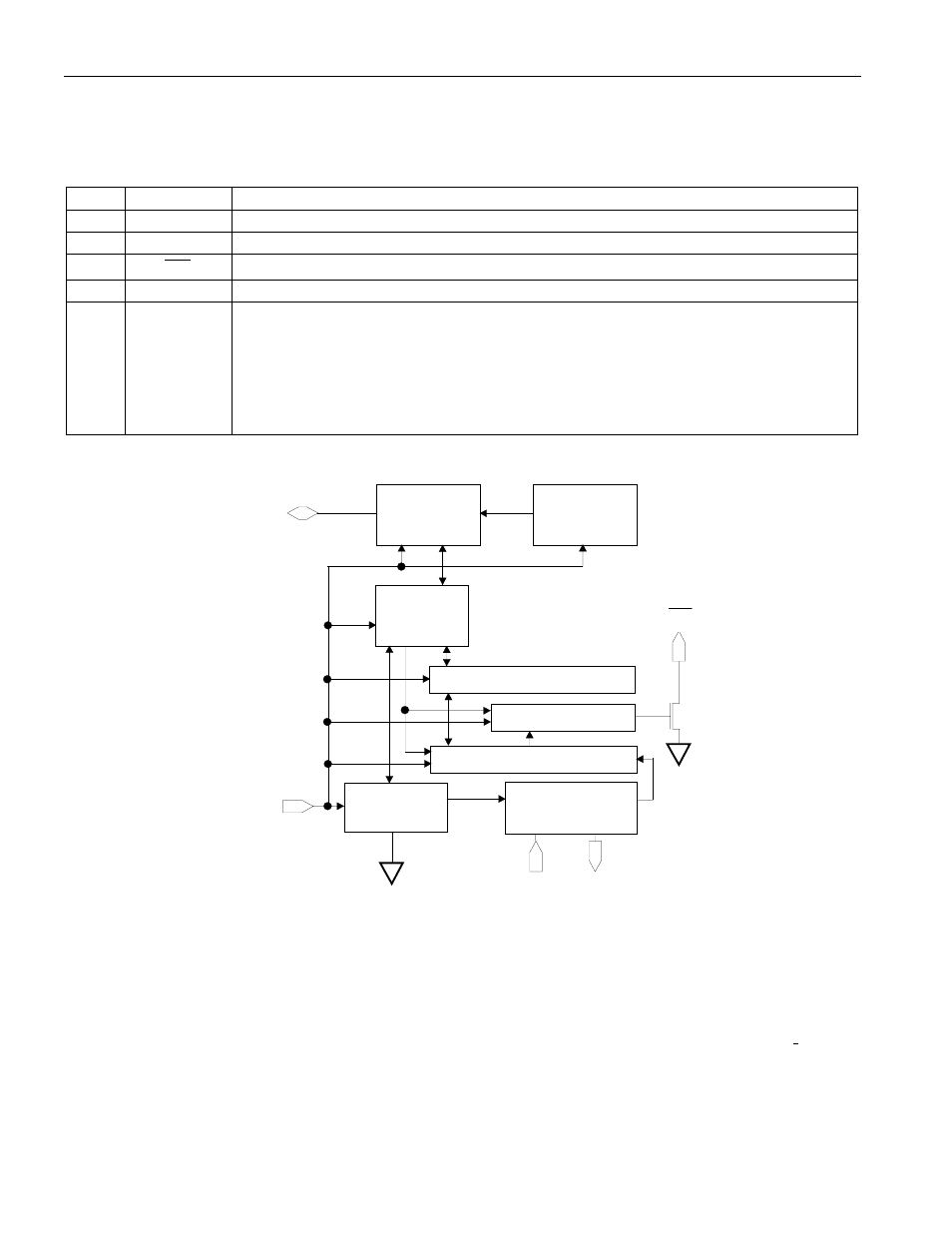
BLOCK DIAGRAM Figure 1
X1
X2
32.768 kHz
OSC./DIVIDER
1-WIRE
ROM
CONTROL
FUNCTION
64-BIT
ROM
LASERED
CLOCK
FUNCTION
CONTROL
RTC COUNTER (32-BIT)
OSCILLATOR
CONTROL
VDD
READ/WRITE BUFFER
1 Hz
INT. GENERATOR
INT\
64-BIT LASERED ROM
Each DS2417 contains a unique ROM code that is 64 bits long. The first eight bits are a 1-Wire family
code. The next 48 bits are a unique serial number. The last eight bits are a CRC of the first 56 bits. (See
Figure 3.) The 1-Wire CRC is generated using a polynomial generator consisting of a shift register and
XOR gates as shown in Figure 4. The polynomial is X
8
+ X
5
+ X
4
+ 1. Additional information about the
Dallas Semiconductor 1-Wire Cyclic Redundancy Check is available in the Book of DS19xx iButton
®
Standards. The shift register bits are initialized to zero. Then starting with the least significant bit of the
family code, one bit at a time is shifted in. After the 8th bit of the family code has been entered, then the
serial number is entered. After the 48th bit of the serial number has been entered, the shift register
contains the CRC value. Shifting in the eight bits of CRC should return the shift register to all zeros. The
INT