Interrupt timing figure 11 – Rainbow Electronics DS2417 User Manual
Page 13
DS2417
13 of 15
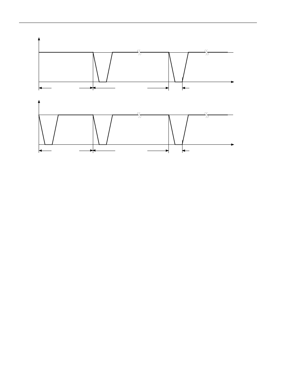
INTERRUPT TIMING Figure 11
Time
= 122 µs
t
INTERVAL
t
PULSE
t
LATENCY
V
INT
Case A: Latency < 0.5
t
INTERVAL
Case B: 0 < Latency <
t
INTERVAL
Time
= 122 µs
t
INTERVAL
t
PULSE
t
LATENCY
V
INT
The latency depends on the selected interrupt interval (IS0 to IS2 settings) and the contents of the RTC
counter at the time of writing the device control byte. In Case A, the flip-flop that determines the interval
duration is reset and toggles before half of the interval time is over. In Case B, this flip-flop is set that
generates an immediate interrupt pulse; the latency, therefore, can be up to one full interval duration.
If enabled, the interrupt pulse may also be triggered while reading from or writing to the control byte.
See also other documents in the category Rainbow Electronics Control panel:
- MAX16840 (1 page)
- MAX9258 (54 pages)
- MAX66140 (21 pages)
- MAX9393 (14 pages)
- MAX66040 (25 pages)
- MAX6981 (1 page)
- MAX6965 (23 pages)
- MAX66100 (16 pages)
- MAX9135 (19 pages)
- MAX66020 (25 pages)
- MAX17127 (22 pages)
- MAX13175E (38 pages)
- MAX16820 (10 pages)
- MAX13237E (16 pages)
- MAX13483E (19 pages)
- MAX13362 (14 pages)
- MAX13486E (16 pages)
- MAX7311 (17 pages)
- MAX8759 (31 pages)
- SCAN92LV090 (13 pages)
- MAX6973 (23 pages)
- MAX13047E (14 pages)
- MAX16831 (20 pages)
- MAX14770E (15 pages)
- MAX11835 (1 page)
- MAX9621 (14 pages)
- MAX9217 (16 pages)
- MAX16841 (18 pages)
- MAX16834 (22 pages)
- MAX7315 (27 pages)
- MAX8645Y (15 pages)
- MAX6975 (23 pages)
- MAX6971 (12 pages)
- MAX3028 (21 pages)
- MAX9395 (13 pages)
- MAX7313 (27 pages)
- MAX6970 (1 page)
- MAX4821 (13 pages)
- MAX4895E (8 pages)
- MAX16823 (13 pages)
- MAX6963 (34 pages)
- MAX9216 (17 pages)
- MAX66000 (21 pages)
- MAX66120 (24 pages)
- MAX13223E (11 pages)