Motor driver ics ba6259n – Rainbow Electronics BA6259N User Manual
Page 3
506
Motor driver ICs
BA6259N
F
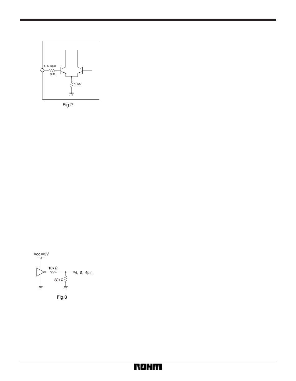
Control pin equivalent circuit
F
Oparation notes
(1)
Use the BA6259N with V
R
(pin 8) short-circuited to
V
CC2
(pin 9). The V
CC2
potential should be lower than the
V
CC1
potential. Under these conditions, the IC provides a
HIGH level output voltage of 11.3V (typical, V
CC2
=12V).
Because a single transistor is used for the low-side out-
put stage, the LOW level output voltage is further low-
ered. This results in a wide range of motor drive voltage.
(2)
Though the IC input pins can be directly connected
with MOS output pins, it is recommendable to connect re-
sistors of a few kiloohms to do3en of kiloohms between
the pins for the sake of pin protection.
(3)
Due to the effects of capacitors C
2
X
C
5
, the motor
that is not being driven could be momentarily driven dur-
ing mode switching. Check for this problem when design-
ing your application.
(4)
It is recommendable to arrange your design so that
voltage rises at V
CC1
prior to V
CC2
when turning on the
power, and voltage falls at V
CC1
after V
CC2
when turning
off the power.
(5)
Thermal shutdown circuit
When the thermal shutdown circuit is activated, the out-
put is left OPEN. The circuit is activated when the IC junc-
tion temperature rises above 170
_
C. The temperature
difference between the activation and deactivation set-
tings is about 30
_
C.
(6)
The quality of these products have been carefully
checked; however, use of the products with applied volt-
ages, operating temperatures, or other parameters that
exceed the absolute maximum rating given may result in
the damage of the IC and the product it is used in. If the
IC is damaged, the short mode and open modes cannot
be specified, so if the IC is to be used in applications
where parameters may exceed the absolute maximum
ratings, then be sure to incorporate fuses, or other physi-
cal safety measures.
(7)
Input pins
Voltage should never be applied to the input pins when
the V
CC
voltage is not applied to the IC. Similarly, when
V
CC
is applied, the voltage on each input pin should be
less than V
CC
and within the guaranteed range for the
electrical characteristics.
(8)
Back-rush voltage
Depending on the ambient conditions, environment, or
motor characteristics, the back-rush voltage may fluctu-
ate. Be sure to confirm that the back-rush voltage will not
adversely affect the operation of the IC.