Input test waveforms and measurement levels, Output test loads, Pin capacitance – Rainbow Electronics ATV22V10BQL User Manual
Page 5: Power-up reset, Preload of registered outputs, Security fuse usage, Atf22v10b(q)(l)
ATF22V10B(Q)(L)
5
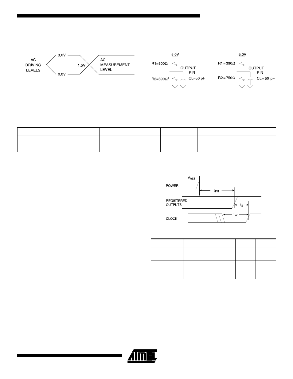
Input Test Waveforms and
Measurement Levels
t
R
, t
F
< 3 ns
Output Test Loads
* All except -7 which is R2 = 300
Ω
Note:
1. Typical values for nominal supply voltage. This parameter is only sampled and is not 100% tested.
Power-up Reset
The registers in the ATF22V10Bs are designed to reset
during power-up. At a point delayed slightly from V
CC
cross-
ing V
RST
, all registers will be reset to the low state. The
output state will depend on the polarity of the output buffer.
This feature is critical for state machine initialization. How-
ever, due to the asynchronous nature of reset and the
uncertainty of how V
CC
actually rises in the system, the
following conditions are required:
1. The V
CC
rise must be monotonic,
2. After reset occurs, all input and feedback setup times
must be met before driving the clock pin high, and
3. The clock must remain stable during t
PR
.
Preload of Registered Outputs
The ATF22V10B’s registers are provided with circuitry to
allow loading of each register with either a high or a low.
This feature will simplify testing since any state can be
forced into the registers to control test sequencing. A
JEDEC file with preload is generated when a source file
with vectors is compiled. Once downloaded, the JEDEC file
preload sequence will be done automatically by most of the
approved programmers after the programming.
Security Fuse Usage
A single fuse is provided to prevent unauthorized copying
of the ATF22V10B fuse patterns. Once programmed, fuse
verify and preload are inhibited. However, the 64-bit User
Signature remains accessible.
The security fuse should be programmed last, as its effect
is immediate.
Commercial
Military
Pin Capacitance
f = 1 MHz, T = 25°C
Typ
Max
Units
Conditions
C
IN
5
8
pF
V
IN
= 0V
C
OUT
6
8
pF
V
OUT
= 0V
Parameter
Description
Typ
Max
Units
t
PR
Power-up
Reset Time
600
1,000
ns
V
RST
Power-up
Reset
Voltage
3.8
4.5
V