Rainbow Electronics DS1615 User Manual
Page 19
DS1615
19 of 24
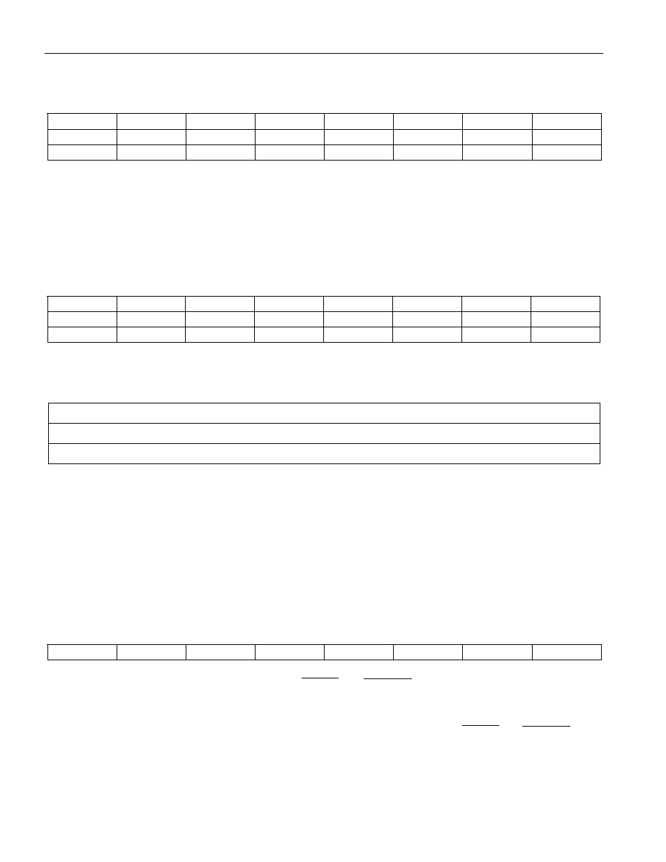
1. Write Byte (22h)
Host Transmit:
D7
D6
D5
D4
D3
D2
D1
D0
0
0
1
0
0
0
1
0
0
a6
a5
a4
a3
a2
a1
a0
d7
d6
d5
d4
d3
d2
d1
d0
DS1615 Response: None
Note that good programming practice insists that the Clear Memory command should be issued whenever
the DS1615 is programmed to begin a new datalogging mission.
2. Read Page (33h)
Host Transmit:
D7
D6
D5
D4
D3
D2
D1
D0
0
0
1
1
0
0
1
1
a15
a14
a13
a12
a11
a10
a9
a8
a7
a6
a5
a4
a3
a2
a1
a0
DS1615 Response (Host Receives):
D7
D6
D5
D4
D3
D2
D1
D0
register a[15..0]
↓
register xxxh
Where xxx represents the last register of the page that has been accessed.
When in asynchronous mode, the TX pin becomes inactive after the last register in the page and the CRC
have been transmitted. In synchronous mode, the DS1615 will continue to transmit data as long as clocks
are presented to the serial interface. If clocks are presented after the final data bit of the last register in
the page, the DS1615 will wrap-around to the first register in the page and sequentially transmit data as
long as the clocks continue.
3. Specification Test (44h)
Host Transmit:
D7
D6
D5
D4
D3
D2
D1
D0
0
1
0
0
0
1
0
0
DS1615 Response (Host Receives): Either the
INSPEC
or
OUTSPEC
pin will generate four low pulses.
Each pulse will be 62.5 ms in duration and will start every half second.
This command instructs the DS1615 to generate four low pulses on either the
INSPEC
or
OUTSPEC
LED
driver pins. The pin that is driven is dependent upon whether any data samples fell outside of the High
Temperature and Low Temperature Threshold boundaries. These pins, when used to drive LEDs, can be
used to provide a quick visual confirmation as to whether the temperature remained within the user-
defined limits.