Rainbow Electronics DS2890 User Manual
Page 5
DS2890
5 of 28
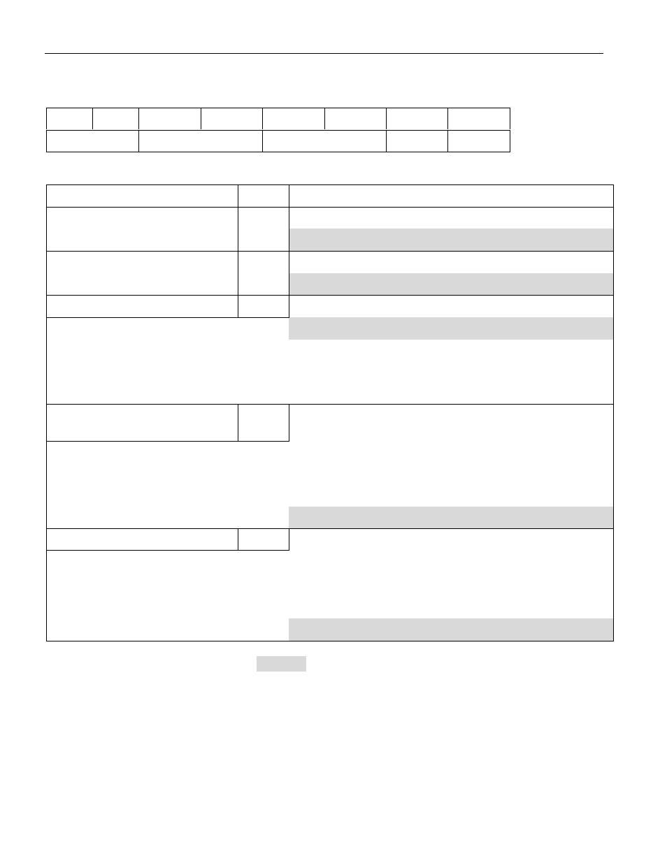
FIGURE 3. 1-WIRE POTENTIOMETER FEATURE REGISTER
Feature Register Bit Encoding
b7
b6
b5
b4
b3
b2
b1
b0
PR
NWP
NP
WSV
PC
Feature Register Bit Definitions
Feature Description
Bit(s)
Definition
If 0: logarithmic potentiometer element(s)
PC: potentiometer characteristic
b0
If 1: linear potentiometer element(s)
If 0: wiper setting(s) are non-volatile
WSV: wiper setting volatility
b1
If 1: wiper setting(s) are volatile
NP: number of potentiometers
b3..b2
2 bit binary value representing number of potentiometers:
If 00b: 1 potentiometer
If 01b: 2 potentiometers
If 10b: 3 potentiometers
If 11b: 4 potentiometers
NWP: number of wiper positions
b5..b4
2 bit binary value representing number of wiper positions
for each potentiometer:
If 00b: 32 positions
If 01b: 64 positions
If 10b: 128 positions
If 11b: 256 positions
PR: potentiometer resistance
b7..b6
2 bit binary value representing potentiometer resistance:
If 00b: 5 k
W
If 01b: 10 k
W
If 10b: 50 k
W
If 11b: 100 k
W
DS2890 feature values are highlighted:
value
The DS2890 will respond with a feature register value of F3h when a READ CONTROL
REGISTER command is executed, see section “POTENTIOMETER FUNCTION COMMANDS”.
POTENTIOMETER CONTROL REGISTER
The potentiometer control register is used to turn on/off the DS2890 charge pump (see section
“POTENTIOMETER WIPER RESISTANCE AND CHARGE PUMP CONSIDERATIONS” for a
discussion of the charge pump) and has control capabilities for future 1-Wire potentiometers that could
contain multiple resistor elements. The format of the control register is shown in Figure 4.