Wire bus system, Hardware configuration, Figure 17. hardware configuration – Rainbow Electronics DS2890 User Manual
Page 14
DS2890
14 of 28
1-WIRE BUS SYSTEM
The 1-Wire bus is a system, which has a single bus master and one or more slaves. In all instances the
DS2890 is a slave device. The bus master is typically a microcontroller. The discussion of this bus system
is broken down into three topics: hardware configuration, transaction sequence, and 1-Wire signaling
(signal types and timing). The 1-Wire protocol defines bus transactions in terms of the bus state during
specific time slots that are initiated on the falling edge of sync pulses from the bus master.
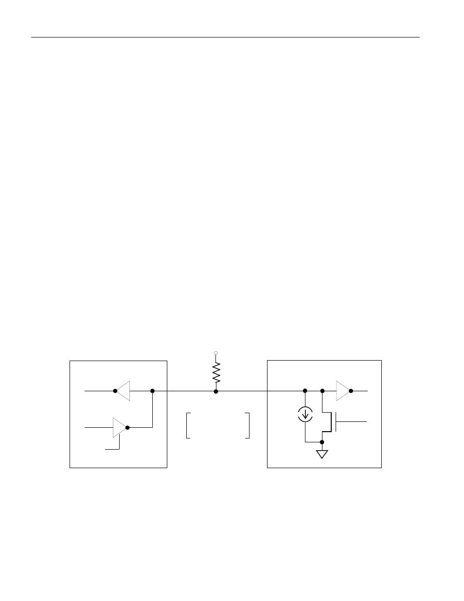
HARDWARE CONFIGURATION
The 1-Wire bus has only a single line by definition; it is important that each device on the bus be able to
drive it at the appropriate time. To facilitate this, each device attached to the 1-Wire bus must have open
drain or 3-state outputs. The 1-Wire port of the DS2890 is open drain with an internal circuit equivalent
to that shown in Figure 9. A multi-drop bus consists of a 1-Wire bus with multiple slaves attached. At
regular speed the 1-Wire bus has a maximum data rate of 16.3 kbits per second. The speed can be boosted
to 142 kbits per second by activating the Overdrive Mode. For a discrete bus master interface as in
Figure 17, the 1-Wire bus requires a pull-up resistor with a minimum value of 2.2 k
W. Depending on
1-Wire communication speed, regular or overdrive, and bus load characteristics, the optimal pull-up
resistor value will be in the 1.5 k
W to 5 kW range. Figure 18 shows a DS2480B bus master configuration
with an interface to the host CPU serial port. Among many features, the DS2480B simplifies the 1-Wire
interface design, generates slew-rate controlled 1-Wire waveforms, and off-loads 1-Wire timing
generation overhead required in a discrete solution.
The idle state for the 1-Wire bus is high. If for any reason a transaction needs to be suspended, the bus
MUST be left in the idle state if the transaction is to resume. If this does not occur and the bus is left low
for more than 16 µs (Overdrive Speed) or more than 120 µs (regular speed), one or more devices on the
bus may be reset.
FIGURE 17. HARDWARE CONFIGURATION
RX
TX
Open Drain
Port Pin
5 µA
Typ.
DS2890 1-WIRE PORT
RX = RECEIVE
TX = TRANSMIT
BUS MASTER
V
PUP
DATA
RX
TX
MOSFET
100
W
See
Text
NOTE:
Depending on 1-Wire communication speed, regular or overdrive, and bus load characteristics, the
optimal pull-up resistor value will be in the 1.5 k
W to 5 kW range.