Pin description, At83c21gc, Figure 2. 24-pin ssop pinout – Rainbow Electronics AT83C21GC User Manual
Page 4: Table 1. port signal description
4
4247CS–SCR–11/05
AT83C21GC
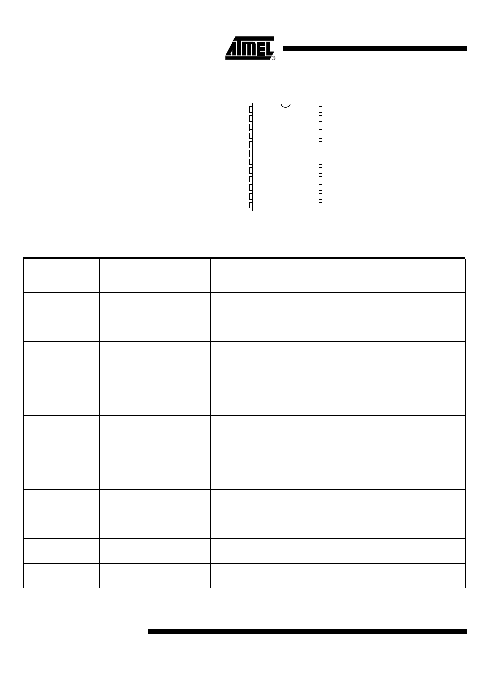
Pin Description
Figure 2. 24-pin SSOP Pinout
P1.1/CC8
P1.4/CCLK
P1.0/CIO
RST
P1.5/CRST
1
P1.3/CC4
P1.2/CPRES
XTAL1
P3.3/INT1/OE
P3.2/INT0
P3.4/T0
P3.5/CIO1/T1
LI
C
V
CC
CVSS
V
CC
E
V
CC
VSS
P3.0/RxD
P3.1/TxD
2
3
4
5
6
7
8
9
10
11
12
24
23
22
21
20
19
18
17
16
15
14
13
P3.6/CCLK1/LED0
XTAL2
P3.7/CRST1/LED1
D
V
CC
SSOP24
Table 1. Port Signal Description
Port
Signal
Name
Internal
Power
Supply
ESD
Type
Description
P1.0
CIO
CV
CC
4 kV
I/O
Smart Card Interface Function
Card I/O – Pull-up medium is lower than 20K
Ω
P1.1
CC8
CV
CC
4 kV
I/O
Smart Card Interface Function
Card contact 8 – Pull-up medium must be less than 20K
Ω
P1.2
CPRES
V
CC
4 kV
I
Smart Card Interface Function
Card presence
P1.3
CC4
CV
CC
4 kV
I/O
Smart Card Interface Function
Card contact 4 – Pull-up medium must be less than 20K
Ω
P1.4
CCLK
CV
CC
4 kV
O
Smart Card Interface Function
Card clock
P1.5
CRST
CV
CC
4 kV
O
Smart Card Interface Function
Card reset – Pull-up medium must be less than 20K
Ω
P3.0
RxD
EV
CC
I
UART Function
Receive data input
P3.1
TxD
EV
CC
O
UART Function
Transmit data output.
P3.2
INT0
DV
CC
I/O
Input/Output Function
P3.2 is a bi-directional I/O port with internal pull-ups.
P3.3
INT1
EV
CC
I/O
Input/Output Function
P3.3 is a bi-directional I/O port with internal pull-ups.
P3.4
EV
CC
I/O
Input/Output Function
P3.4 is a bi-directional I/O port with internal pull-ups.
P3.5
CIO1
DV
CC
I/O
Alternate Card Function
Card I/O: Pull-up medium must be less than 20K