Electrical characteristics (continued) – Rainbow Electronics MAX15054 User Manual
Page 3
High-Side MOSFET Driver for HB LED Drivers
and DC-DC Applications
MAX15054
_______________________________________________________________________________________ 3
ELECTRICAL CHARACTERISTICS (continued)
(V
DD
= V
BST
= 5V, V
LX
= V
GND
= 0V, T
A
= T
J
= -40°C to +125°C, unless otherwise noted. Typical values are at T
A
= T
J
= +25°C,
unless otherwise noted.) (Note 2)
Note 2: All devices are 100% production tested at T
A
= +25NC. Limits over the operating temperature range are guaranteed by
design.
Note 3: Guaranteed by design.
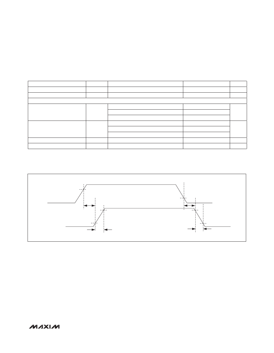
Figure 1. Turn-On/Turn-Off Propagation Delay
PARAMETER
SYMBOL
CONDITIONS
MIN
TYP
MAX
UNITS
Peak Output Current (Sourcing)
I
PK_HP
V
HDRV
= 0V
2.5
A
Peak Output Current (Sinking)
I
PK_HN
V
HDRV
= 5V
2.5
A
SWITCHING CHARACTERISTICS
Rise Time
t
R
No-load capacitor
1.5
ns
C
L
= 1000pF
6
C
L
= 5000pF
18
Fall Time
t
F
No-load capacitor
1.5
ns
C
L
= 1000pF
6
C
L
= 5000pF
16
Turn-On Propagation Delay
t
D_ON
Figure 1, C
L
= 1000pF (Note 3)
11
25
ns
Turn-Off Propagation Delay
t
D_OFF
Figure 1, C
L
= 1000pF (Note 3)
11
25
ns
V
HI
V
IH
V
IL
t
D_OFF
t
F
t
D_ON
10%
90%
t
R
V
HDRV