Table 1. 4-wire serial interface truth table – Rainbow Electronics MAX6934 User Manual
Page 9
MAX6922/MAX6932/MAX6933/MAX6934
27-, 28-, and 32-Output, 76V,
Serial-Interfaced VFD Tube Drivers
_______________________________________________________________________________________
9
clocked in are loaded. Therefore, multiple devices can
share CLK and DIN, as long as they have unique LOAD
controls.
Determining Driver Output Voltage Drop
The outputs are CMOS drivers, and have a resistive
characteristic. The typical and maximum sink and
source output resistances can be calculated from the
V
H
and V
L
electrical characteristics. Use this calculated
resistance to determine the output voltage drop at dif-
ferent output currents.
Output Current Ratings
The continuous current-source capability is 40mA per
output. Outputs may drive up to 75mA as a repetitive
peak current, subject to the on-time (output high) being
no longer than 1ms, and the duty cycle being such that
the output power dissipation is no more than the dissipa-
tion for the continuous case. The repetitive peak rating
allows outputs to drive a higher current in multiplex grid
driver applications, where only one grid is on at a time,
and the multiplex time per grid is no more than 1ms.
Since dissipation is proportional to current squared, the
maximum current that can be delivered for a given mul-
tiplex ratio is given by:
I
PEAK
= (grids x 1600)
1/2
mA
where grids is the number of grids in a multiplexed
display.
This means that a duplex application (two grids) can use
a repetitive peak current of 56.5mA, a triplex (three grids)
application can use a repetitive peak current of 69.2mA,
and higher multiplex ratios are limited to 75mA.
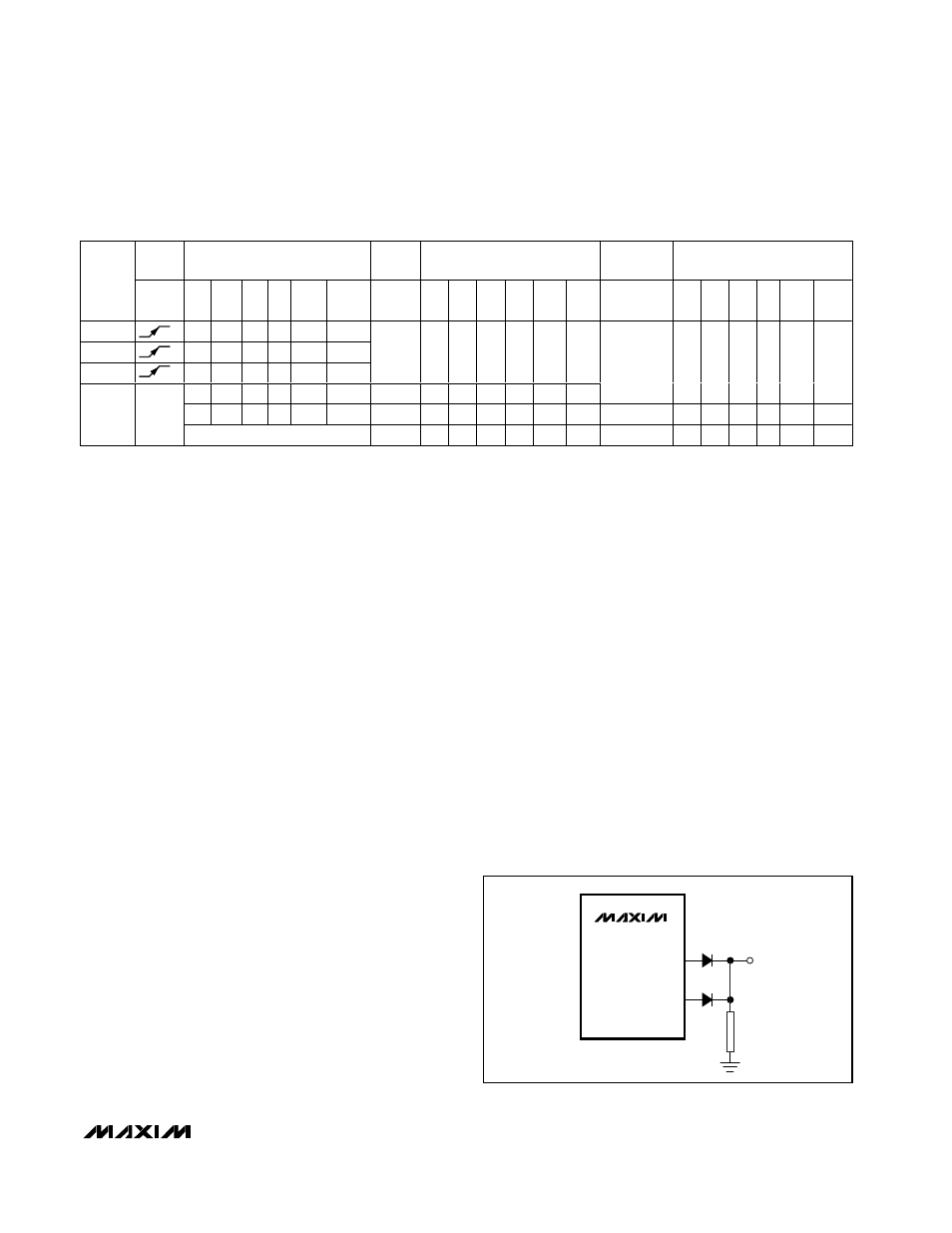
Paralleling Outputs
Any number of outputs within the same package may
be paralleled in order to raise the current drive or
reduce the output resistance. Only parallel outputs
directly (by shorting outputs together) if the interface
control can be guaranteed to set the outputs to the
same level. Although the sink output is relatively weak
(typically 750Ω), that resistance is low enough to dissi-
pate 530mW when shorted to an opposite level output
at a V
BB
voltage of only 20V. A safe way to parallel out-
puts is to use diodes to prevent the outputs from sink-
ing current (Figure 5). Because the diodes also stop
the outputs from sinking current from the VFD tube, an
external discharge resistor, R, is required. For static
tubes, R can be a large value such as 100kΩ. For multi-
plexed tubes, the value of the resistor can be deter-
mined by the load capacitance and timing
MAX6922
MAX6932
MAX6933
MAX6934
OUT0
OUT1
D1
D2
R
OUTPUT
Figure 5. Paralleling Outputs
L = Low logic level.
H = High logic level.
X = Don’t care.
P = Present state (shift register).
R = Previous state (latched).
CLOCK
INPUT
SHIFT REGISTER CONTENTS
LOAD
INPUT
LATCH CONTENTS
BLANKING
INPUT
OUTPUT CONTENTS
SERIAL
DATA
INPUT
DIN
CLK
D0
D1
D2 … Dn-2 Dn-1
LOAD
D0 D1
D2
… Dn-2 Dn-1
BLANK
D0 D1 D2 … Dn-2 Dn-1
H
H
R0
R1 … Rn-2
Rn-1
L
L
R0
R1 … Rn-2
Rn-1
X
R0
R1
R2 … Rn-1
Rn
X
X
X
…
X
X
L
R0
R1
R2
… Rn-1
Rn
P0
P1
P2 … Pn-1
Pn
H
P0
P1
P2
… Pn-1
Pn
L
P0
P1
P2 … Pn-1
Pn
X
X
X
…
X
X
H
L
L
L
…
L
L
Table 1. 4-Wire Serial Interface Truth Table