Pin description (continued) – Rainbow Electronics MAX15022 User Manual
Page 9
MAX15022
Dual, 4A/2A, 4MHz, Step-Down DC-DC
Regulator with Dual LDO Controllers
_______________________________________________________________________________________
9
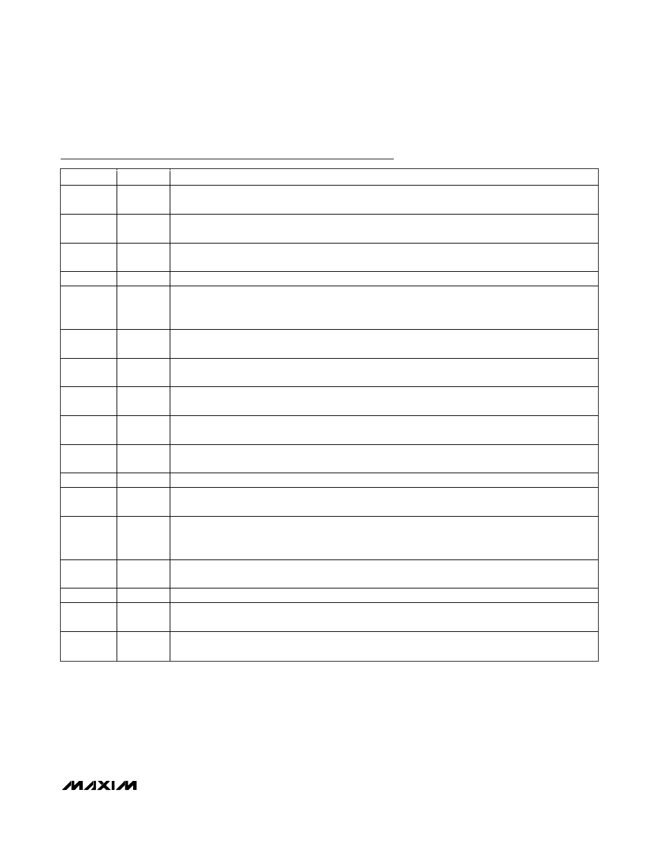
Pin Description (continued)
PIN
NAME
FUNCTION
13
B3
Transconductance Amplifier Open-Drain Output for LDO Controller 3. Connect B3 to the base of an
external PNP transistor to regulate output 3.
14
FB3
Feedback Regulation Point for LDO Controller 3. Connect to the center tap of a resistive divider from the
output 3 to SGND to set the output voltage. The FB3 voltage regulates to 0.6V (typ).
15
EN3
LDO Enable Input for LDO Controller 3. EN3 must exceed 1.225V (typ) for the LDO controller to begin
regulating output 3.
16
DVDD2
Switch Driver Supply for Regulator 2. Connect externally to PVIN2.
17
PGND2
Power Ground Connection for Regulator 2. Connect the negative terminals of the input and output filter
capacitors to PGND2. Connect PGND2 externally to SGND at a single point, typically at the negative
terminal of the input bypass capacitor.
18
LX2
Inductor Connection for Regulator 2. LX2 is the drain connection of the internal high-side p-channel
MOSFET and the drain connection of the internal synchronous n-channel MOSFET for Regulator 2.
19
PVIN2
Input Supply Voltage for Regulator 2. Connect to an external voltage source from 2.5V to 5.5V. Bypass
PVIN2 to PGND2 with a 1μF (min) ceramic capacitor.
20
EN4
LDO Enable Input for LDO Controller 4. EN4 must exceed 1.225V (typ) for the LDO controller to begin
regulating output 4.
21
FB4
Feedback Regulation Point for LDO Controller 4. Connect to the center tap of a resistive divider from
output 4 to SGND to set the output voltage. The FB4 voltage regulates to 0.6V (typ).
22
B4
Transconductance Amplifier Open-Drain Output for LDO Controller 4. Connect B4 to the base of an
external PNP transistor to regulate output 4.
23
COMP2
Error-Amplifier Output for Regulator 2. Connect COMP2 to the compensation feedback network.
24
FB2
Feedback Regulation Point for Regulator 2. Connect to the center tap of a resistive divider from the
regulator 2 output to SGND to set the output voltage. The FB2 voltage regulates to 0.6V (typ).
25
EN2
Enable Input for Regulator 2. When configured as a sequencer, EN2 must exceed 1.225V (typ) for the
PWM controller to begin regulating output 1. When configured as a tracker, connect EN2 to the center
tap of a resistive divider from the regulator 1 output.
26
SGND
Signal Ground. Connect SGND to PGND_ at a single point, typically near the negative terminal of the
input bypass capacitor.
27
AVIN
Input Voltage. Bypass AVIN to SGND with a 100nF (min) ceramic capacitor.
28
RT
Oscillator Timing Resistor Connection. Connect a 4.2k
Ω to 33kΩ resistor from RT to SGND to program
the switching frequency from 500kHz to 4MHz.
—
EP
Exposed Paddle. Connect EP to a large copper plane at SGND potential to improve thermal dissipation.
Do not use as the main SGND connection.