Pwm controllers design procedure – Rainbow Electronics MAX15022 User Manual
Page 14
MAX15022
Dual, 4A/2A, 4MHz, Step-Down DC-DC
Regulator with Dual LDO Controllers
14
______________________________________________________________________________________
Error Amplifier
The output of the internal voltage-mode error amplifier
(COMP_) is provided for frequency compensation (see
the
Compensation Design Guidelines
section). FB_ is
the inverting input of the error amplifier. The error
amplifier has an 80dB open-loop gain and a 12MHz
gain bandwidth (GBW) product.
Output Short-Circuit
Protection (Hiccup Mode)
The MAX15022 features lossless, high-side peak cur-
rent limit and low-side, valley current limit. At short duty
cycles, both limits are active. At high duty cycles, only
the high-side peak current limit is active. Either limit
causes the hiccup mode counter (N
CL
) to increment.
For duty cycles less than 50%, the low-side valley cur-
rent limit is active. Once the high-side MOSFET turns off,
the voltage across the low-side MOSFET is monitored. If
this voltage does not exceed the current-limit threshold
at the end of the cycle, the high-side MOSFET turns on
normally at the start of the next cycle. If the voltage
exceeds the current-limit threshold just before the
beginning of a new PWM cycle, the controller skips that
cycle. During severe overload or short-circuit condi-
tions, the switching frequency of the device appears to
decrease because the on-time of the low-side MOSFET
extends beyond a clock cycle.
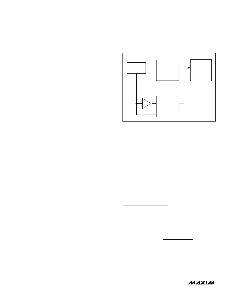
If the current-limit threshold is exceeded for more than
four cumulative clock cycles (N
CL
), the device shuts
down for 8192 clock cycles (hiccup timeout) and then
restarts with a soft-start sequence. If three consecutive
cycles pass without a current-limit event, the count of
N
CL
is cleared (see Figure 3). Hiccup mode protects
the device against a continuous output short circuit.
The internal current limit is constant from 5.5V down to
3V and decreases linearly by 50% from 3V to 2V. See
the
Electrical Characteristics
table.
Thermal-Overload Protection
The MAX15022 features an integrated thermal-overload
protection with temperature hysteresis. Thermal-over-
load protection limits the die temperature of the device
and protects it in the event of an extended thermal fault
condition. When the die temperature exceeds +160°C,
an internal thermal sensor shuts down the device, turn-
ing off the internal power MOSFETs and allowing the die
to cool. After the die temperature falls by +15°C (typ),
the device restarts with a soft-start sequence.
Startup into a Prebiased Output
(Sequencing Mode)
In sequencing mode, the regulators start with minimal
glitch into a prebiased output and soft-stop is disabled.
During soft-start, both switches are kept off until the
PWM comparator commands its first PWM pulse. Until
then, the converters do not sink current from the out-
puts. The first PWM pulse occurs when the ramping ref-
erence voltage increases above the FB_ voltage.
LDO Controllers
The MAX15022 provides two additional LDO controllers
to drive external PNP pass transistors. Connect the emit-
ter of each PNP pass transistor to either the input supply
or one of the controller 1 or 2 outputs. Each LDO con-
troller features an independent enable input and digital
soft-start. Connect FB3 and FB4 to the center tap of a
resistive divider from the output of the desired LDO con-
troller to SGND to set the output voltage.
PWM Controllers
Design Procedure
Setting the Switching Frequency
Connect a 4.2k
Ω to 33kΩ resistor from RT to SGND to
program the switching frequency (f
SW
) from 500kHz to
4MHz. Calculate the required resistor value R
RT
to set
the switching frequency with the following equation:
Higher frequencies allow designs with lower inductor
values and less output capacitance. At higher switch-
ing frequencies core losses, gate-charge currents,
and switching losses increase. When operating from
V
AVIN
< 3V, the f
SW
frequency should be derated to
3MHz (maximum).
R
f
[kHz] 1
[V]
32
4[MHz]
RT
SW
[
]
.
[
]
k
A
Ω =
Ч
Ч
067
μ
CURRENT LIMIT
COUNT OF 4
N
CL
IN
CLR
INITIATE HICCUP
TIMEOUT
N
HT
COUNT OF 3
N
CLR
IN
CLR
Figure 3. Hiccup-Mode Block Diagram