Electrical characteristics (continued) – Rainbow Electronics MAX5974D User Manual
Page 3
MAX5974A/MAX5974B/MAX5974C/MAX5974D
Active-Clamped, Spread-Spectrum,
Current-Mode PWM Controllers
3
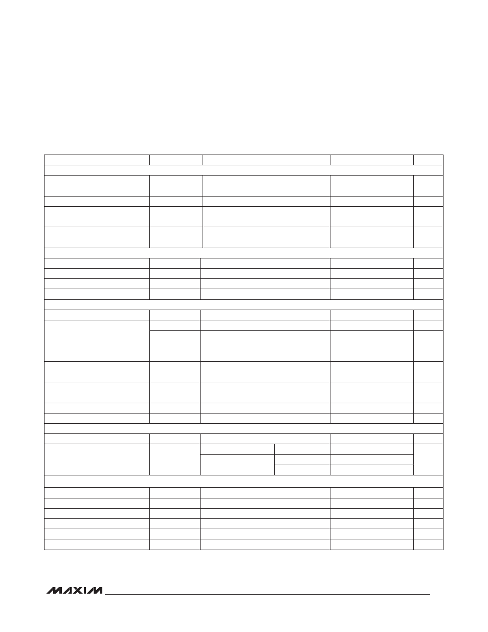
ELECTRICAL CHARACTERISTICS (continued)
(V
IN
= 12V (for MAX5974A/MAX5974C, bring V
IN
up to 21V for startup), V
CS
= V
CSSC
= V
DITHER/SYNC
= V
FB
= V
FFB
= V
DCLMP
=
V
GND
, V
EN
= +2V, NDRV = AUXDRV = SS = COMP = unconnected, R
RT
= 34.8kI, R
DT
= 25kI, C
IN
= 1FF, T
A
= -40NC to +85NC,
unless otherwise noted. Typical values are at T
A
= +25NC.) (Note 2)
PARAMETER
SYMBOL
CONDITIONS
MIN
TYP
MAX
UNITS
SYNCHRONIZATION (SYNC)
Synchronization Logic-High
Input
V
IH-SYNC
2.91
V
Synchronization Pulse Width
50
ns
Synchronization Frequency
Range
f
SYNCIN
1.1 x
f
SW
2 x
f
SW
kHz
Maximum Duty Cycle During
Synchronization
D
MAX
x f
SYNC
/
f
SW
%
DITHERING RAMP GENERATOR (DITHER)
Charging Current
V
DITHER
= 0V
45
50
55
F
A
Discharging Current
V
DITHER
= 2.2V
43
50
57
F
A
Ramp’s High Trip Point
2
V
Ramp’s Low Trip Point
0.4
V
SOFT-START AND RESTART (SS)
Charging Current
I
SS-CH
9.5
10
10.5
F
A
Discharging Current
I
SS-D
V
SS
= 2V, normal shutdown
0.65
1.34
2
mA
I
SS-DH
(V
EN
< V
ENF
or V
IN
< V
INUVF
),
V
SS
= 2V, hiccup mode discharge for
t
RESTART
(Note 3)
1.6
2
2.4
F
A
Discharge Threshold to Disable
Hiccup and Restart
V
SS-DTH
0.15
V
Minimum Restart Time During
Hiccup Mode
t
RSTRT-MIN
1024
Clock
Cycles
Normal Operating High Voltage
V
SS-HI
5
V
Duty-Cycle Control Range
V
SS-DMAX
D
MAX
(typ) = (V
SS-DMAX
/2.43V)
0
2
V
DUTY-CYCLE CLAMP (DCLMP)
DCLMP Input Current
I
DCLMP
V
DCLMP
= 0 to 5V
-100
0
+100
nA
Duty-Cycle Control Range
V
DCLMP-R
V
DCLMP
= 0.5V
73
75.4
77.5
%
D
MAX
(typ) =
1 - (V
DCLMP/
2.43V)
V
DCLMP
= 1V
54
56
58
V
DCLMP
= 2V
14.7
16.5
18.3
NDRV DRIVER
Pulldown Impedance
R
NDRV-N
I
NDRV
(sinking) = 100mA
1.9
3.4
I
Pullup Impedance
R
NDRV-P
I
NDRV
(sourcing) = 50mA
4.7
8.3
I
Peak Sink Current
1
A
Peak Source Current
0.65
A
Fall Time
t
NDRV-F
C
NDRV
= 1nF
14
ns
Rise Time
t
NDRV-R
C
NDRV
= 1nF
27
ns