Rainbow Electronics MAX5974D User Manual
Page 18
MAX5974A/MAX5974B/MAX5974C/MAX5974D
Active-Clamped, Spread-Spectrum,
Current-Mode PWM Controllers
18
Oscillator/Switching Frequency
The ICs’ switching frequency is programmable between
100kHz and 600kHz with a resistor R
RT
connected
between RT and GND. Use the following formula to
determine the appropriate value of R
RT
needed to gen-
erate the desired output-switching frequency (f
SW
):
9
RT
SW
8.7 10
R
f
×
=
where f
SW
is the desired switching frequency.
Peak Current Limit
The current-sense resistor (R
CS
in the Typical
Application Circuits), connected between the source
of the n-channel MOSFET and PGND, sets the current
limit. The current-limit comparator has a voltage trip level
(V
CS-PEAK
) of 400mV. Use the following equation to cal-
culate the value of R
CS
:
CS
PRI
400mV
R
I
=
where I
PRI
is the peak current in the primary side of
the transformer, which also flows through the MOSFET.
When the voltage produced by this current (through the
current-sense resistor) exceeds the current-limit com-
parator threshold, the MOSFET driver (NDRV) terminates
the current on-cycle, within 35ns (typ).
The devices implement 115ns of leading-edge blanking
to ignore leading-edge current spikes. These spikes
are caused by reflected secondary currents, current-
discharging capacitance at the FET’s drain, and gate-
charging current. Use a small RC network for additional
filtering of the leading-edge spike on the sense wave-
form when needed. Set the corner frequency between
10MHz and 20MHz.
After the leading-edge blanking time, the device moni-
tors V
CS
for any breaches of the peak current limit of
400mV. The duty cycle is terminated immediately when
V
CS
exceeds 400mV.
Reverse Current Limit
The devices protect the transformer against saturation
due to reverse current by monitoring the voltage across
R
CS
while the AUX output is low and the p-channel FET
is on.
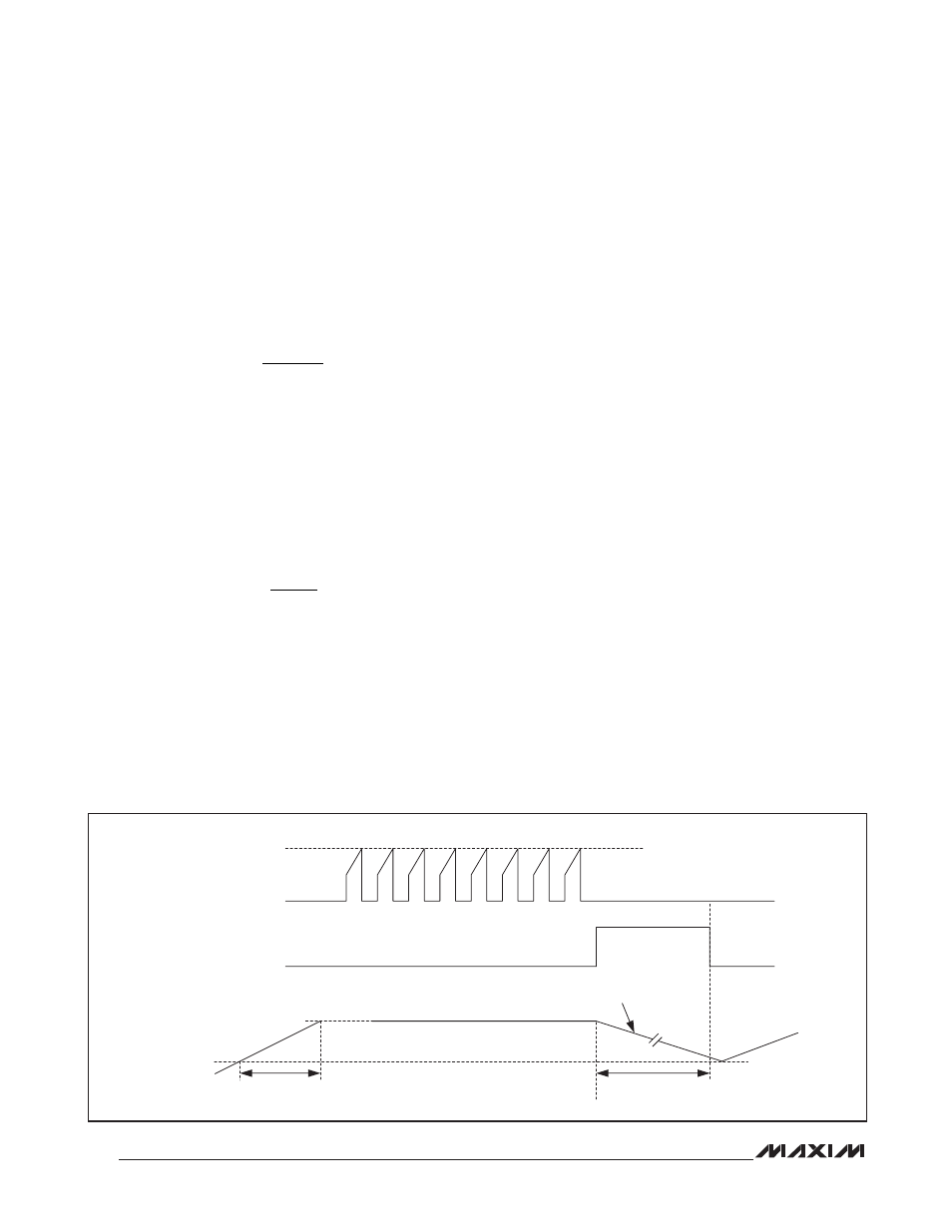
Output Short-Circuit Protection
with Hiccup Mode
When the device detects eight consecutive peak current-
limit events, both NDRV and AUXDRV driver outputs are
turned off for a restart period, t
RSTRT
. After t
RSTRT
, the
device undergoes soft-start. The duration of the restart
period depends on the value of the capacitor at SS (C
SS
).
During this period, C
SS
is discharged with a pulldown cur-
rent of I
SS-DH
(2FA typ). Once its voltage reaches 0.15V,
the restart period ends and the device initiates a soft-start
sequence. An internal counter ensures that the minimum
restart period (t
RSTRT-MIN
) is 1024 clock cycles when the
time required for C
SS
to discharge to 0.15V is less than
1024 clock cycles. Figure 4 shows the behavior of the
device prior and during hiccup mode.
Figure 4. Hiccup Mode Timing Diagram
V
CSBL
(BLANKED CS
VOLTAGE)
V
CS-PEAK
(400mV)
HICCUP
DISCHARGE WITH I
SS-DH
V
SS-DTH
SOFT-START
VOLTAGE,
V
SS
V
SS-HI
t
RSTRT
t
SS