Pin configuration pin description – Rainbow Electronics MAX5974D User Manual
Page 11
MAX5974A/MAX5974B/MAX5974C/MAX5974D
Active-Clamped, Spread-Spectrum,
Current-Mode PWM Controllers
11
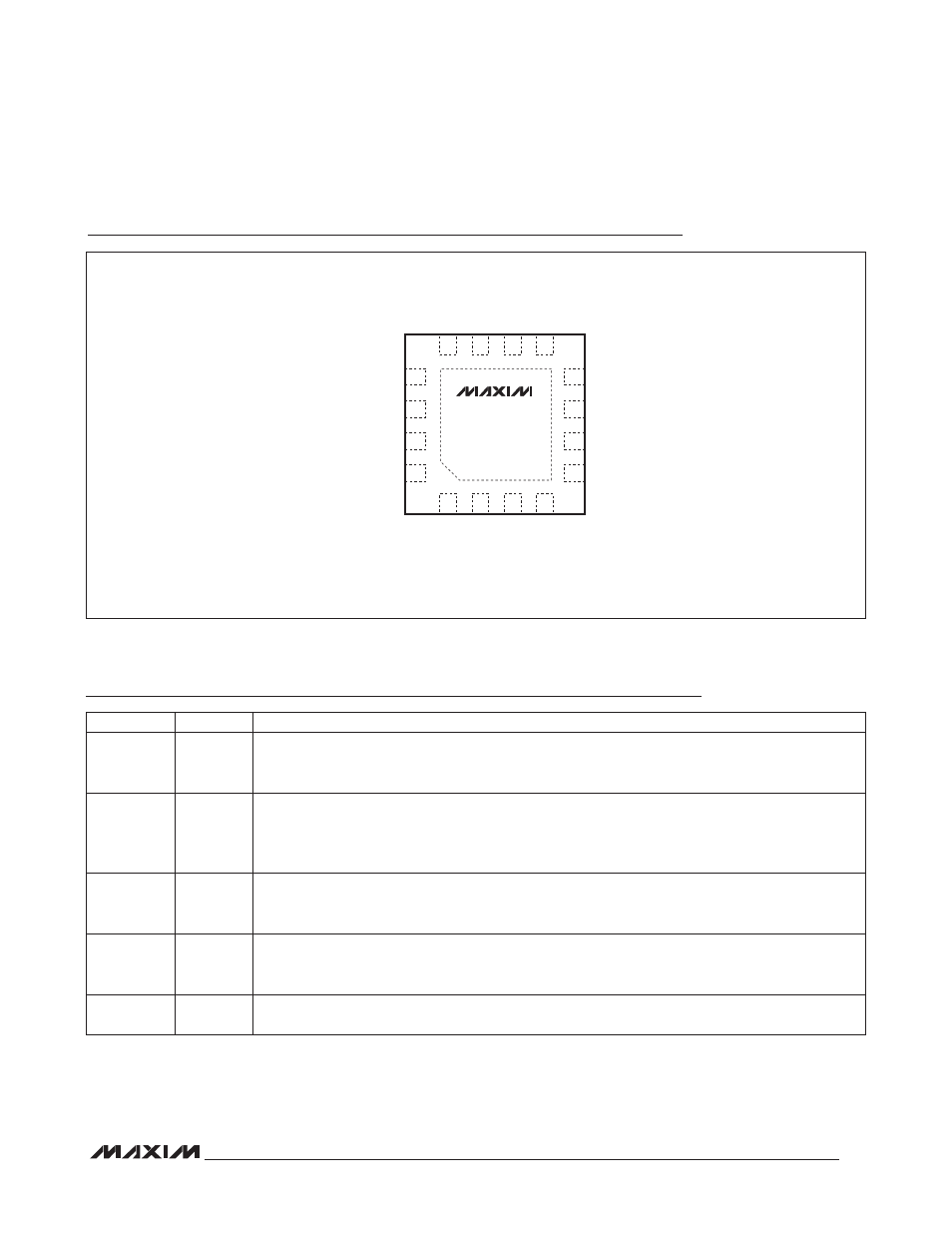
Pin Configuration
Pin Description
15
16
14
13
5
6
7
RT
FFB
8
DT
PGND
CS
AUXDRV
1
3
EN
4
12
10
9
DCLMP
SS
CSSC
GND
FB
COMP
EP
MAX5974A
MAX5974B
MAX5974C
MAX5974D
DITHER/
SYNC
NDRV
2
11
IN
THIN QFN
TOP VIEW
+
PIN
NAME
FUNCTION
1
DT
Dead-Time Programming Resistor Connection. Connect resistor R
DT
from DT to GND to set the
desired dead time between the NDRV and AUXDRV signals. See the Dead Time section to calcu-
late the resistor value for a particular dead time.
2
DITHER/
SYNC
Frequency Dithering Programming or Synchronization Connection. For spread-spectrum frequency
operation, connect a capacitor from DITHER to GND and a resistor from DITHER to RT. To syn-
chronize the internal oscillator to the externally applied frequency, connect DITHER/SYNC to the
synchronization pulse.
3
RT
Switching Frequency Programming Resistor Connection. Connect resistor R
RT
from RT to GND to
set the PWM switching frequency. See the Oscillator/Switching Frequency section to calculate the
resistor value for the desired oscillator frequency.
4
FFB
Frequency Foldback Threshold Programming Input. Connect a resistor from FFB to GND to set the
output average current threshold below which the converter folds back the switching frequency to
1/2 of its original value. Connect to GND to disable frequency foldback.
5
COMP
Transconductance Amplifier Output and PWM Comparator Input. COMP is level shifted down and
connected to the inverting input of the PWM comparator.