Table 8. register 00h: audio control, Table 9. register 07h: tv video output control, Table 10. register 08h: vcr video input control – Rainbow Electronics MAX9597 User Manual
Page 27
MAX9597
Low-Power Audio/Video Interface
for Single SCART Connectors
______________________________________________________________________________________
27
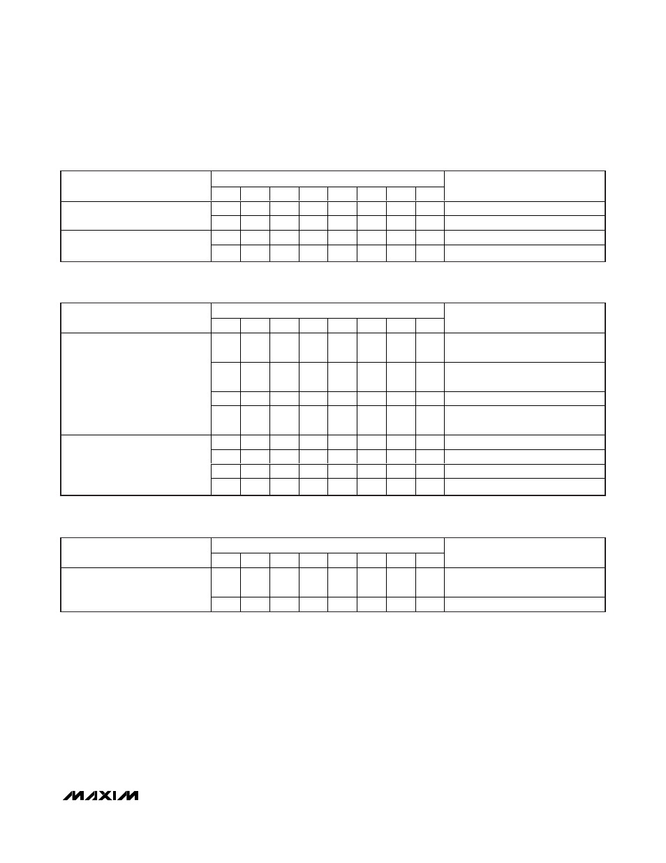
BIT
DESCRIPTION
7
6
5
4
3
2
1
0
COMMENTS
—
—
—
—
—
—
—
0
Off
TV audio mute
—
—
—
—
—
—
—
1
On (power-on default)
—
0
—
—
—
—
—
—
Off
Zero-crossing detector
—
1
—
—
—
—
—
—
On (power-on default)
Table 8. Register 00h: Audio Control
BIT
DESCRIPTION
7
6
5
4
3
2
1
0
COMMENTS
—
—
—
—
—
—
0
0
Low (< 2V) internal source (power-on
default)
—
—
—
—
—
—
0
1
Medium (4.5V to 7V) external SCART
source with 16:9 aspect ratio
—
—
—
—
—
—
1
0
High impedance
Set TV slow switching
—
—
—
—
—
—
1
1
High ( > 9.5V) external SCART source
with 4:3 aspect ratio
—
—
—
0
0
—
—
—
GND (power-on default)
—
—
—
0
1
—
—
—
Not used
—
—
—
1
0
—
—
—
Same level as VCR_FB_IN
Set TV fast switching
—
—
—
1
1
—
—
—
V
VID
Table 9. Register 07h: TV Video Output Control
BIT
DESCRIPTION
7
6
5
4
3
2
1
0
COMMENTS
—
—
—
—
0
—
—
—
DC restore clamp active at input
(power-on default)
ENC_R/C_IN clamp/bias
—
—
—
—
1
—
—
—
Chrominance bias applied at input
Table 10. Register 08h: VCR Video Input Control